Improved buttonholing machine tool

A buttonhole machine and buttonhole technology, applied in the direction of cloth pressing mechanism, sewing machine components, sewing machine control devices, etc., can solve the problems of difficult adjustment, extremely high requirements for assemblers, complex structure of rotating parts, etc. The effect of reducing the difficulty of debugging, reducing assembly requirements and debugging difficulty, and improving the efficiency of assembly and debugging

Active Publication Date: 2012-01-04
SHANGHAI WEISHI MACHINERY
View PDF5 Cites 11 Cited by
  • Summary
  • Abstract
  • Description
  • Claims
  • Application Information

AI Technical Summary

Problems solved by technology

[0005] One is that the spinning clamping structure has its own structural characteristics. When the upper clamping foot is turned over, a shearing force tangential to the rotation direction of the pressing foot will be generated on the fabric, and the fabric will be subjected to a vertical downward force. In addition to the pressure component force, there is also a horizontal component force, the cloth will be displaced under this force component, and the positioning that should be accurate becomes no longer accurate; the keyhole machine tool originally relies on three sets of components to press the cloth for positioning. However, due to the downward shearing force caused by the rotary downward pressure method used in the component structure, the fabric that needs to be precisely positioned is more or less displaced
The displacement caused by the three shearing forces at the same time will cause serious deviation of the cloth, so that the straightness of the buttonhole of the machine cannot be effectively guaranteed when the buttonhole is buttonholed
At present, customers have put forward very high requirements on the straightness of the buttonhole machine, and some customers have even proposed that the straightness should be kept within 0.25mm, and the requirements will become higher and higher in the future. Obvio

Method used


Image

  • Improved buttonholing machine tool
  • Improved buttonholing machine tool
  • Improved buttonholing machine tool

Examples


Embodiment Construction

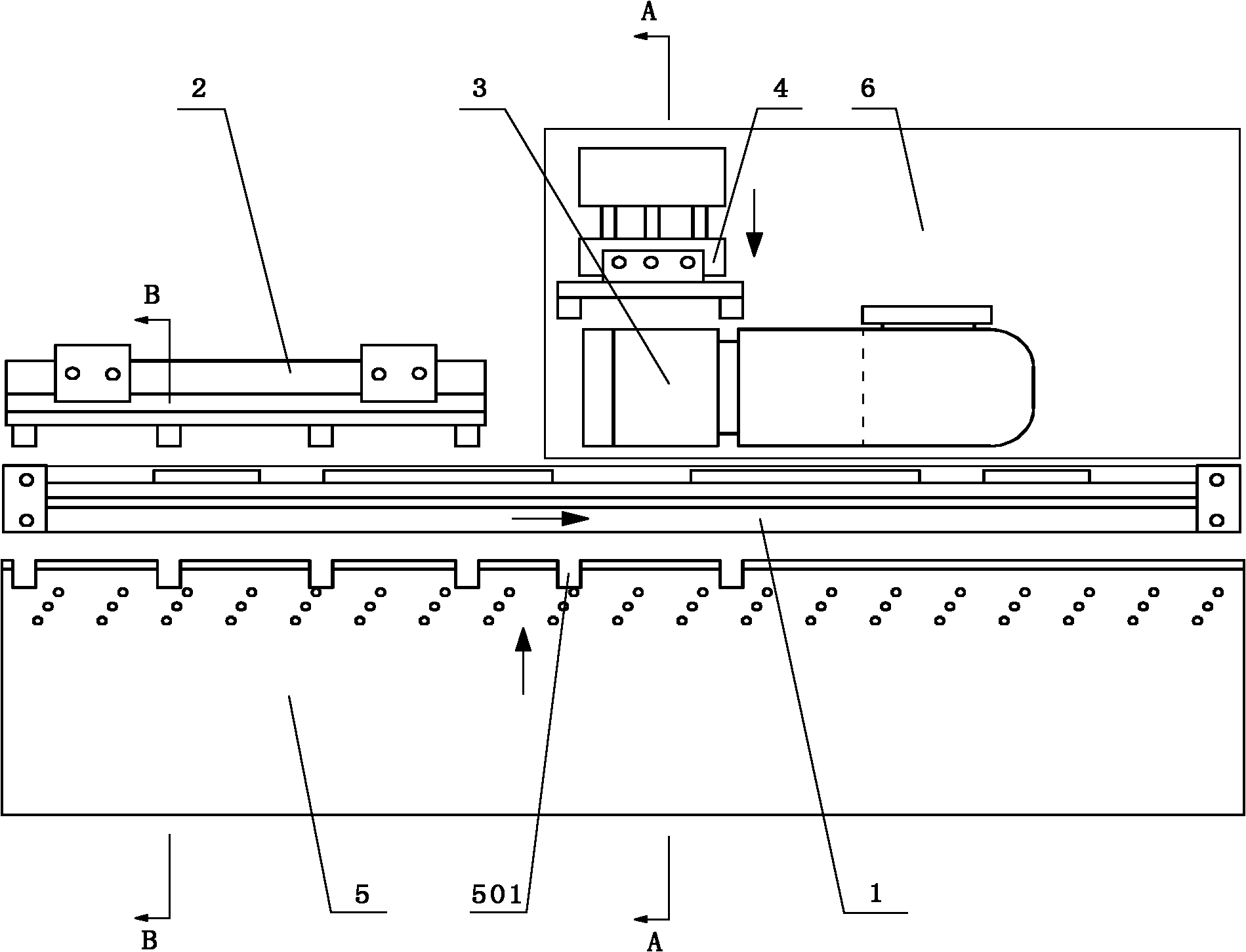
[0039] The present invention will be further described below in conjunction with accompanying drawing, and the arrow direction in the figure is the action direction of each moving part.

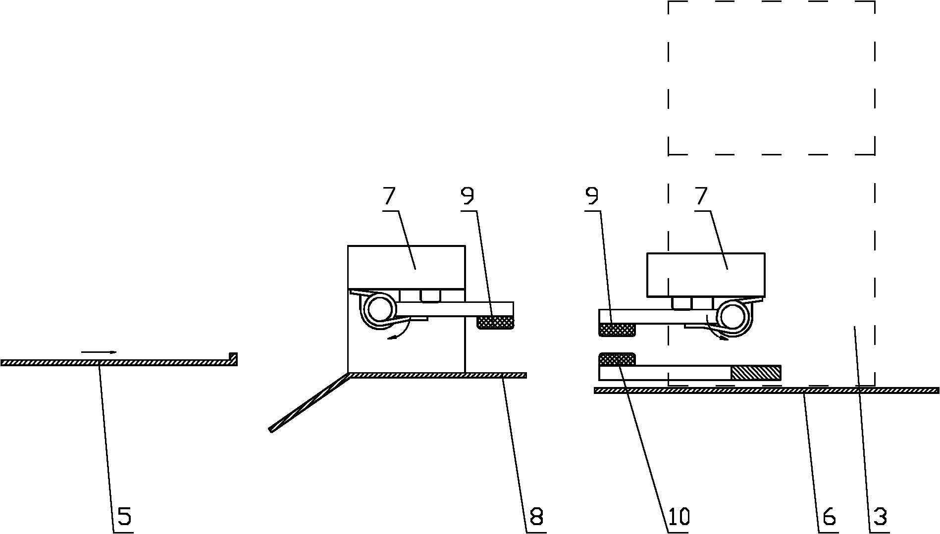
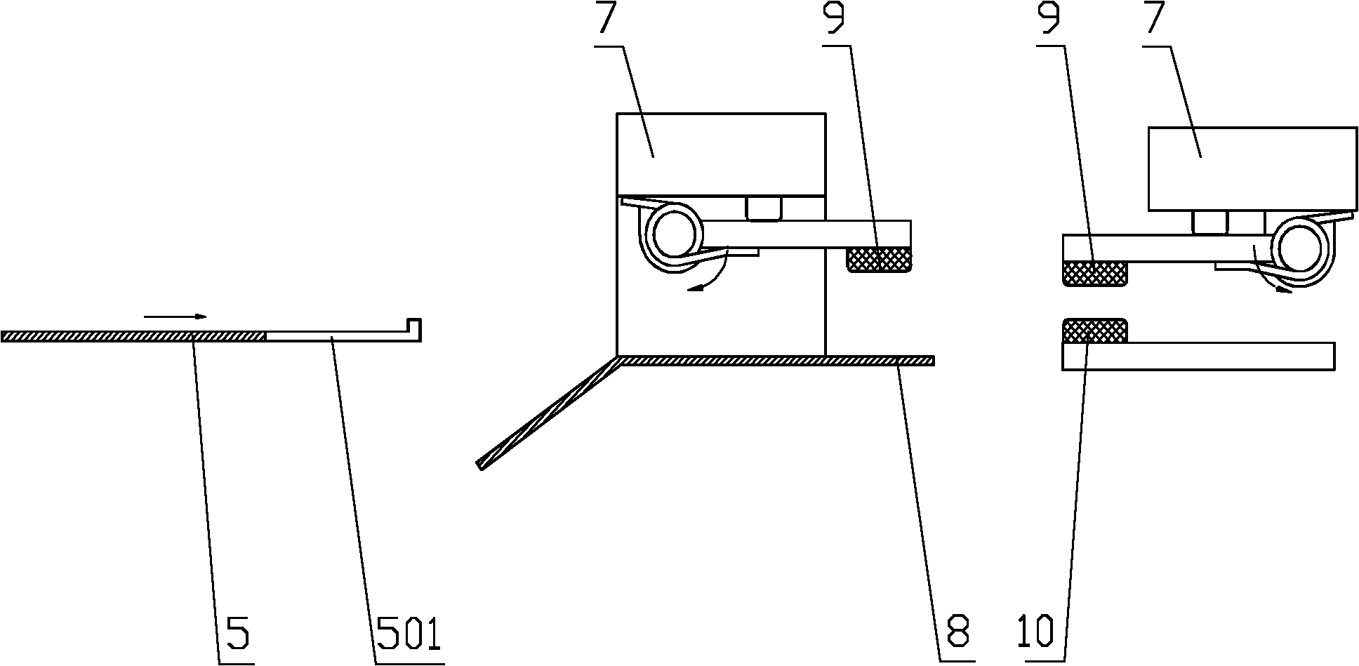
[0040] figure 1 Among them, the shirt placket buttonhole buttonhole machine tool includes a horizontally arranged rectangular feeding plate 5 and a pressing and feeding assembly 1 located on the rear side of the pressing and feeding assembly 1. The buttonhole machine 3, the buttonhole machine 3 is fixed on the horizontal work surface 6 below it in an inverted "L" shape, there is a space between the bottom of the buttonhole machine 3 head and the work table 6, the rear side of the buttonhole machine 3 head Arrange the head pressing assembly 4.

[0041] The pressing and feeding assembly 1 includes an upper pressing foot 9 and a lower supporting plate 8 arranged up and down, and the upper pressing foot 9 and the lower supporting plate 8 can be opened / closed; the main pressing assembly 2 and the...


PUM


Abstract

The invention discloses an improved buttonholing machine tool. The improved buttonholing machine tool comprises a horizontally arranged rectangular feeding plate and a compaction feeding assembly which is positioned on the rear side of the rectangular feeding plate; a main compaction assembly and a buttonholing machine are parallelly arranged on the rear side of the compaction feeding assembly left and right; a machine head compaction assembly is distributed on the rear side of the head of the buttonholing machine; the compaction feeding assembly comprises upper compaction pins and a lower material supporting plate which are arranged vertically; the upper compaction pins and the lower material supporting plate can be opened or closed; the main compaction assembly and the machine head compaction assembly comprise a plurality of pairs of upper and lower compaction pins which are arranged along the length direction at intervals respectively; and the upper compaction pins and the lower compaction pins can be opened or closed; and the upper compaction pins of three sets of compaction positioning assemblies are driven by an air cylinder to vertically lift. A clamping positioning structure which is vertically pressed improves straightness of a button hole of a front fly of shirts, and guarantees the aesthetic feeling of the front fly of shirts; the mechanical structure is greatly simplified, the assembly difficulty and debugging difficulty are reduced, and the mechanical assembly efficiency and the maintenance cost of a customer are improved conveniently; and the buttonholing machine tool guarantees that the stress surface is full when fabric is compacted and has a better compaction effect.

Description

technical field [0001] The invention relates to a buttonhole machine tool for shirt placket buttonholes, in particular to the clamping and positioning of cloth. Background technique [0002] At present, the existing automatic high-speed buttonhole machine tools produced by Japan Heavy Machinery Co., Ltd. are widely used and have relatively good performance. The machine tool has three sets of pressing and feeding components: the main pressing unit, the head pressing unit, and the pressing and feeding unit. These three sets of components all adopt the idea of ​​rotating and pressing: [0003] The pressing and feeding assembly includes upper and lower arrangement, openable / closable upper pressing foot and lower support plate, the main pressing assembly and machine head pressing assembly include multiple opening / closing For the upper and lower pressing feet, the opening / closing of the three sets of components is realized by turning over the upper pressing foot. When closed, t...

Claims


Application Information

Patent Timeline
IPC IPC(8): D05B3/06D05B29/06D05B69/10
Inventor 吕立毅柴国宣王国顺黄小伟狄金刚
Owner SHANGHAI WEISHI MACHINERY
Why Eureka
Try Eureka