Tower for multi-rotor wind generating system

A wind power generation system, multi-rotor technology, applied in wind turbine components, wind turbine control, wind power generation, etc., can solve the problem of inability to use cost, little significance, and it is difficult to avoid collision between blades and towers or supporting structures, etc. problem, to achieve the effect of reducing cost and small deflection

Inactive Publication Date: 2012-01-04
TIANJIN UNIV
View PDF5 Cites 5 Cited by
  • Summary
  • Abstract
  • Description
  • Claims
  • Application Information

AI Technical Summary

Problems solved by technology

[0003] At present, the common wind turbines on the market have a structure that a wind turbine is installed on the top of an upright tower. For such a structure, since the blades used are relatively long compared to the tower, the lowest point of the blades is close to the ground, resulting in It is not possible to use a lower-cost mast tower in the design of the tower. Even if the mast tower is used, it is of little significance, resulting in a higher cost of the tower
At the same time, the longer the blade, the greater the deflection, so the truss structure that occupies a large space is not suitable
[0004] In the existing patents, it is proposed to arrange a plurality of small and medium-sized wind turbines on the tower, and each wind turbine rotates independently to face the wind. In this way, most of the time, some wind turbines are always in the position of other wind turbines or towers. The wake area of ​​the wind turbine affects the power generation efficiency. At the same time, it is difficult to avoid the collision between the blades and the tower or supporting structure when the wind turbine and the tower are doing relative rotary motion.

Method used


Image

  • Tower for multi-rotor wind generating system
  • Tower for multi-rotor wind generating system
  • Tower for multi-rotor wind generating system

Examples


Embodiment Construction

[0024] The present invention will be described in further detail below in conjunction with the accompanying drawings. The following detailed description is only descriptive, not restrictive, and cannot limit the protection scope of the present invention.

[0025] The present invention will be further described below in conjunction with the accompanying drawings.

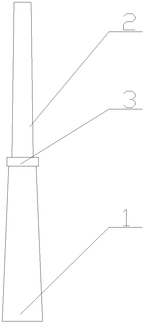
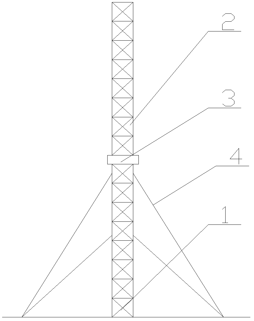
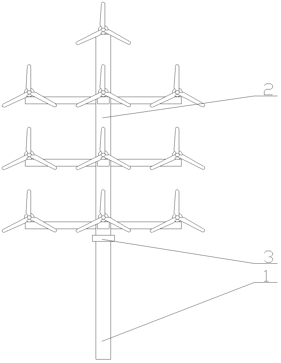
[0026] A tower for a multi-rotor wind power generation system includes a lower tower 1, an upper tower 2, and a slewing drive device 3, and the slewing drive device is arranged between the upper tower and the lower tower.

[0027] The lower tower is a cylinder, cone, segmented cylinder or truss structure, and the upper tower is a cylinder, cone, segmented cylinder or truss structure.

[0028] The truss structure is triangular, quadrilateral, pentagonal, hexagonal or octagonal, and the rods of the truss structure are angle steel, I-beam, channel steel, square tube and / or round tube.

[0029] The surface of the lower ...


PUM


Abstract

The invention discloses a tower for a multi-rotor wind generating system. The tower comprises a lower tower (1), an upper tower (2) and a rotary driving device (3), wherein the rotary driving device is arranged between the upper tower and the lower tower. The tower has the advantages that: (1) the rotary driving device arranged in the middle of the towers can integrally rotate a plurality of wind turbines arranged to fulfill the aims of wind facing, casting off and safe protection and ensure that the plurality of wind turbines cannot influence one another in the wind direction and partial wind turbines cannot be positioned in wake flow areas of other wind turbines, or towers or beams so as to furthest utilize wind energy; (2) a slewing bearing or a rotary driving device in a cabin in the prior art is eliminated; because the rotary driving device is arranged between the upper tower and the lower tower realizes wind facing, yawing and safe protection functions, the slewing bearing or the rotary driving system is not required to be arranged in a cabin of a single wind turbine; and (3) the cost of the tower is reduced.

Description

technical field [0001] The invention belongs to the field of wind energy utilization, and relates to a tower used for a multi-rotor wind power generation system. Background technique [0002] With the global energy crisis and the aggravation of global environmental pollution, many countries have paid more attention to the research, development and utilization of clean and renewable energy. The Global Wind Energy Council pointed out that compared with other renewable energy technologies, wind power technology is more mature, its efficiency is higher, the industry has the best prospect, and its development and utilization growth rate is much higher than that of conventional energy. One of the fastest growing renewable energy technologies. [0003] At present, the common wind turbines on the market have a structure that a wind turbine is installed on the top of an upright tower. For such a structure, since the blades used are relatively long compared to the tower, the lowest p...

Claims


Application Information

Patent Timeline
Patent Type & Authority Applications(China)
IPC IPC(8): F03D11/00F03D7/00
CPCY02E10/723Y02E10/722Y02E10/72Y02P70/50
Inventor 王一平朱丽黄群武
Owner TIANJIN UNIV
Why Eureka
Try Eureka