Stator lamination stacking workbench

A technology of stator punching and workbench, which is applied in the direction of workbench, manufacturing stator/rotor body, manufacturing tools, etc. It can solve the problems that the positioning rod cannot automatically adjust the height, the stacking of punching pieces is inconvenient, and the degree of automation is low. Reliable stacking process, improved stacking efficiency, and reduced labor intensity

Inactive Publication Date: 2012-01-04
SHANGHAI FANUC ROBOTICS
View PDF5 Cites 5 Cited by
  • Summary
  • Abstract
  • Description
  • Claims
  • Application Information

AI Technical Summary

Problems solved by technology

Since the height of the positioning rod cannot be automatically adjusted, it is very inconvenient for the workers to stack the punching sheets, the work efficiency is low, and the degree of automation is low

Method used


Image

  • Stator lamination stacking workbench
  • Stator lamination stacking workbench
  • Stator lamination stacking workbench

Examples


Embodiment Construction

[0024] In order to better understand the technical solution of the present invention, it will be described in detail below through specific embodiments in conjunction with the accompanying drawings:

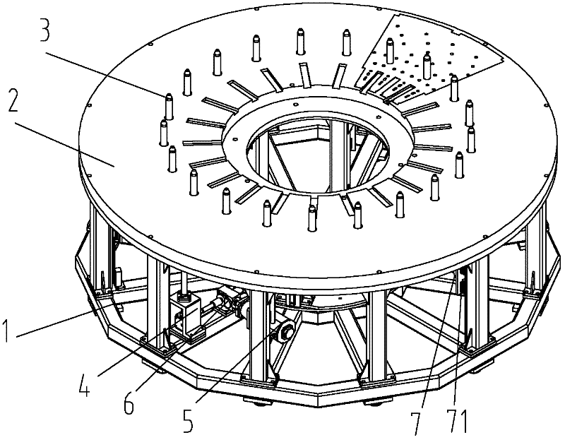
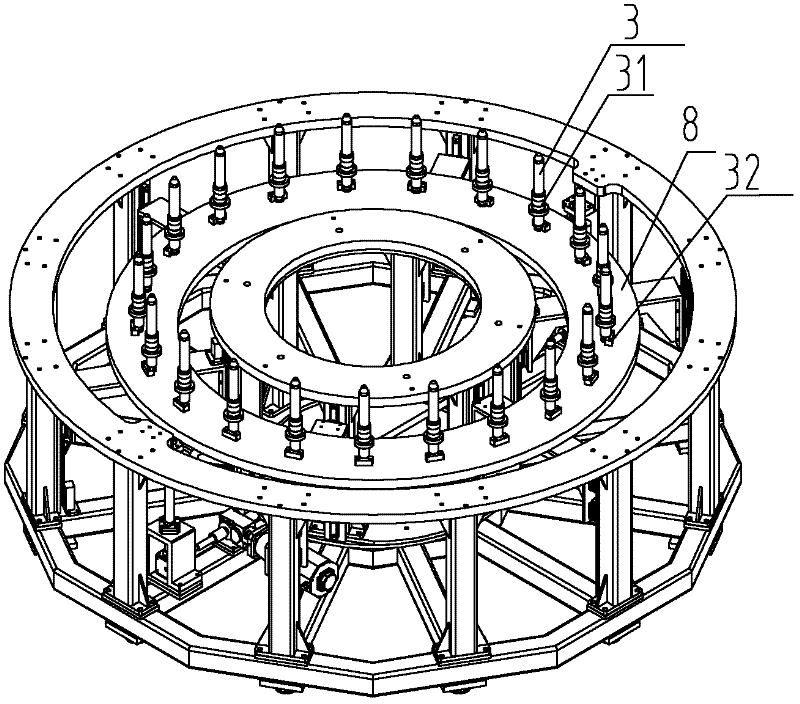
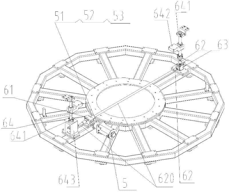
[0025] see figure 1 , figure 2 , image 3 and combine Figure 4 , a stacking workbench for stator punching of the present invention includes a stacking platform body 1, a stacking table top 2 and 21 positioning rods 3, and it also includes a positioning device 4, which includes a fixed connection The transmission device 6 driven by the servo motor 5 on the stacked platform body 1, a lifting bracket 7 with a linear guide rail 71 installed vertically, and an annular lifting plate 8 supported by the lifting bracket 7, wherein,

[0026] The number of positioning rods 3 is determined according to the difference of the stator punches, such as 21, 19 or 22. In the present embodiment, there are 21 positioning rods 3, which are evenly distributed on the ring-shaped lifting plate 8, an...


PUM


Abstract

The invention discloses a stator lamination stacking workbench, which comprises a stacking platform body, a stacking workbench tabletop and a plurality of positioning rods. The workbench further comprises a positioning device. The positioning device comprises a transmission device driven by a servo motor, a lifting bracket vertically provided with linear guide rails and an annular lifting plate supported by the lifting bracket. By the stator lamination stacking workbench, power is provided by the servo motor and transmitted by a precision reducer, a servo special coupling, a precision steering gear and a precision ball screw, and action guidance is performed by the linear guide rails to realize the accurate positioning of the positioning rods, thereby realizing the automation of stator lamination stacking operations, reducing cost and improving production efficiency.

Description

technical field [0001] The invention relates to a workbench for stacking and stacking stator punching pieces. Background technique [0002] At present, the stacking of stator punching sheets in domestic power station equipment manufacturing enterprises adopts a simple fixed stacking platform and is completed by manual operation. Since the positioning rod cannot automatically adjust the height, it is very inconvenient for the workers to stack the punching sheets, the work efficiency is low, and the degree of automation is low. At the same time, because the positioning accuracy of the fixed stacking platform is not high, it cannot meet the requirements of the generator set. During the stacking process, a second manual positioning is required to adjust the positional uniformity of the punching sheet, so it cannot meet the production of modern high-tech products. The need is an urgent problem for people in the industry to solve. Contents of the invention [0003] The purpose...

Claims


Application Information

Patent Timeline
Patent Type & Authority Applications(China)
IPC IPC(8): H02K15/02B25H1/00
Inventor 田文兴陈竟新李广伟任令章
Owner SHANGHAI FANUC ROBOTICS
Why Eureka
Try Eureka