
Pleura biopsy puncture sampling brush

A technique for pleural biopsy and puncture needle, which is applied to trocars and other directions, can solve the problems of low success rate of sampling and inspection, and achieve the effects of simple structure, reasonable design and increased possibility

Inactive Publication Date: 2012-01-11
孙逊
View PDF3 Cites 2 Cited by
  • Summary
  • Abstract
  • Description
  • Claims
  • Application Information

AI Technical Summary

Problems solved by technology

[0003] The purpose of the present invention is to provide a puncture sampling brush for pleural biopsy to solve the problem that the success rate of the puncture needle sampling test is too low for patients with pleural effusion

Method used


Image

  • Pleura biopsy puncture sampling brush
  • Pleura biopsy puncture sampling brush

Examples


Embodiment 1

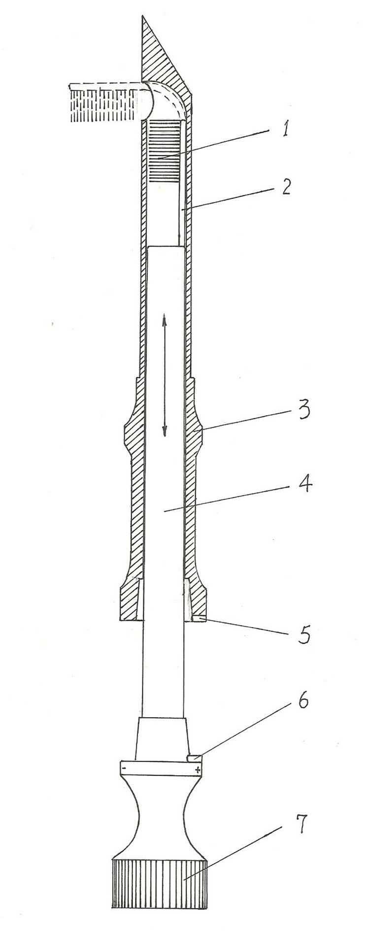
[0013] like figure 1 As shown, the present invention includes three parts: a puncture needle barrel 3 , a needle bar 4 and a brush positioned at the front end of the needle bar 4 . The front end of the puncture needle cylinder 3 is the puncture tip, and the outer periphery of the rear part is a reinforced section for easy gripping. The top opening of the core hole of the puncture needle cylinder 3 is opened at the front end of the puncture needle cylinder after being turned by not less than 90° on the side wall. Because if the steering angle is less than 90°, the protruding brush will be in an upwardly inclined posture, which is not conducive to scraping the inner wall of the pleural cavity. Therefore, it is advisable to generally control the turning angle of the top opening of the core hole of the puncture needle barrel 3 at 91-95°.

[0014] The needle bar 4 is in the shape of a round rod with a straight handle. A control handle 7 is connected to the lower end of the needle...

Embodiment 2

[0017] like figure 1 As shown, the present invention includes three parts: a puncture needle barrel 3 , a needle bar 4 and a brush positioned at the front end of the needle bar 4 . The front end of the puncture needle cylinder 3 is the puncture tip, and the outer periphery of the rear part is a reinforced section for easy gripping. The top opening of the core hole of the puncture needle cylinder 3 is opened at the front end of the puncture needle cylinder after being turned by not less than 90° on the side wall.

[0018] The needle bar 4 is in the shape of a round rod with a straight handle, and a control handle 7 is connected to the lower end of the needle bar 4, and positioning marks are engraved on the outer surface of the control handle 7 and the lower end outer surface of the puncture needle barrel 3 respectively. In addition, radial positioning marking lines are engraved on the lower part of the needle bar 4 to determine the initial position of the needle bar advance; a...


PUM


Abstract

The invention relates to a pleura biopsy puncture sampling brush, structurally comprising a puncture needle drum with the front end being a sharp end, and a needle rod connected in a core hole of the puncture needle drum in an inserting manner, wherein a top opening of the core hole of the puncture needle drum is opened on the side wall of the front end of the puncture needle drum after rotating by an angle not less than 90 degrees; the top part of the needle rod is connected with an elastic brush rod axially extending out; and brushing hair extending out transversely towards one side is connected on the elastic brush rod. In the pleura biopsy puncture sampling brush, the pleura tissue cells around the puncture point are brushed by utilizing planar rotation of a hair brush, so that the planar sampling with circular sweeping of the hair brush is realized, the sampling area is greatly increased, and the possibility of finding out the characteristic tissue cells is also increased. After clinical trial, the one-time sampling success rate can reach more than 40%. In the pleura biopsy puncture sampling brush, the structure is simple, the design is reasonable, and the sampling is reliable; and when the pleura biopsy puncture sampling brush is used for pleura biopsy sampling, the wound surface is small, the pain of a patient is less, and the restoration is easy.

Description

technical field [0001] The invention relates to a device for biopsy, in particular to a pleural biopsy puncture sampling brush. Background technique [0002] Clinically, for patients with pleural effusion, in order to find the cause of pleural effusion, biopsy sampling is usually used for pathological examination. The biopsy sampling method of pleural effusion is usually sampled with a pleural biopsy needle. In this sampling method, generally only 2-3 tissue samples can be taken blindly with a crochet needle inserted into the pleural cavity through a puncture needle. The causative factors can be determined; however, it is generally difficult to precisely align the puncture point with the characteristic lesion of the patient, so sampling the non-characteristic lesion in the patient's pleural cavity cannot determine the cause of the pleural effusion. Clinically, the success rate of determining the causative factors by puncture needle sampling for pleural effusion is generall...

Claims


Application Information

Patent Timeline
IPC IPC(8): A61B10/02
Inventor 孙逊
Owner 孙逊
Learn More