
Pneumatic tire

A pneumatic tire and tire technology, applied in special tires, tire parts, tire tread/tread pattern, etc., can solve the problem of wet performance, snow performance, uneven wear resistance, and reduced snow performance, etc. Improve wet performance and snow performance, ensure drainage performance, and improve uneven wear resistance

Active Publication Date: 2012-01-11
THE YOKOHAMA RUBBER CO LTD
View PDF4 Cites 22 Cited by
  • Summary
  • Abstract
  • Description
  • Claims
  • Application Information

AI Technical Summary

Problems solved by technology

However, if the tire has a directional tread pattern that specifies the direction of rotation of the tire, since the direction of rotation of the tire is fixed, the rotation can only be performed between the front and rear wheels mounted on the same side on both sides of the vehicle
Therefore, for tires such as light truck tires that bear a large load on the shoulders during rotation, when the above-mentioned directional tread pattern is used, the tires can only be rotated between the front and rear wheels on the same side, and it is impossible to prevent the tire from rotating. Uneven wear on the tire shoulders
In addition, in order to suppress uneven wear, it is effective to reduce lateral grooves and increase block rigidity, but at this time, snow performance may be reduced
Therefore, it is difficult to balance wet performance, snow performance and uneven wear resistance

Method used


Image

  • Pneumatic tire
  • Pneumatic tire
  • Pneumatic tire

Examples


example

[0062] 11 kinds of pneumatic tires of Conventional Example 1, Comparative Examples 1-2, and Examples 1-8 were produced. The tire sizes were 195 / 75R16C and 107 / 105R, and the different specifications were shown in Tables 1 and 2.

[0063] These 11 kinds of tires are assembled on the 16×51 / 2J rim, the front wheel is inflated to 280kPa, and the rear wheel is inflated to 450kPa, and then installed on European trucks with a maximum load capacity of 3.5 tons, and the resistance is measured by the following method Uniform wear, water drainage, wet handling stability, and snow handling stability.

[0064] Uneven wear resistance

[0065] After running 4000 km on an asphalt road with the above-mentioned vehicle, the appearance of the tire was visually evaluated. The evaluation results were expressed with the value of Conventional Example 1 as an index of 100. The smaller the index value, the better the uneven wear resistance.

[0066] Drainage performance

[0067] Use the above-menti...


PUM


Abstract

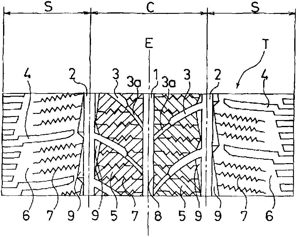
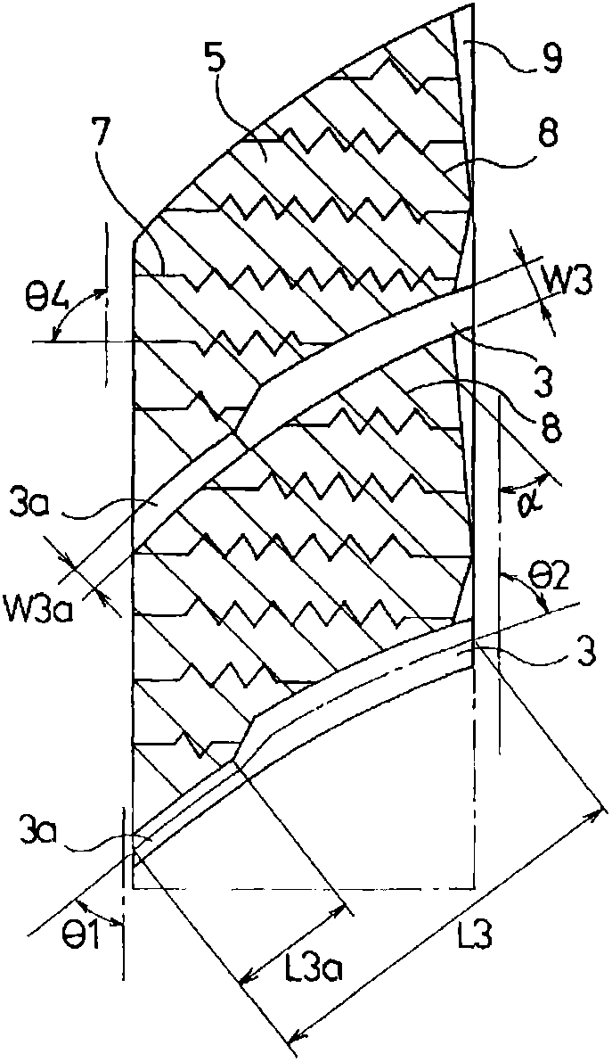
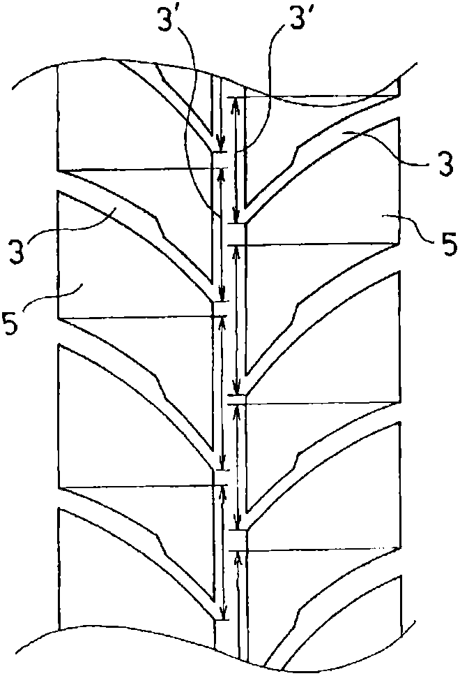
The invention provides a pneumatic tire, which has directional patterns and achieves improved wet performance, snow performance and nonuniform wear resistance. The central portion (C) of the pneumatic tire is divided into multiple pattern blocks (5) via a central main groove (1), outer main grooves (2) and transverse grooves (3). Meanwhile, the strip-shaped patterns (5) at the tire shoulder portion (S) is provided with shoulder pattern grooves (4). The patterns of the pneumatic tire are directional patterns. The transverse grooves (3) are formed at two sides of the central main groove (1) in the tire width direction and is reversely inclined relative to the tire equator, wherein the central inclined angle Theta1 of the transverse grooves (3) is an acute angle. Meanwhile, the transverse grooves (3) are formed at two sides of the central main groove (1) in the tire width direction and the tire circumferential direction in a staggered manner such that the circumferential portion (3') formed by upward projection of the transverse grooves (3) in the tire circumferential direction is provided at the periphery of the tire. In addition, sipes (7) are provided at the pattern blocks (5) and the strip-shaped patterns (6).

Description

technical field [0001] The present invention relates to a pneumatic tire, and more particularly, to a pneumatic tire capable of improving wet performance and snow performance and improving uneven wear resistance. Background technique [0002] As is known to all, dividing a tire into multiple blocks by means of a plurality of main grooves extending along the tire circumferential direction and a plurality of transverse grooves extending along the tire width direction can have excellent snow performance and drainage performance. In this type of pneumatic tire, a directional tread pattern is used on the tread for higher drainage performance. For example, Patent Document 1 proposes to form a tread pattern as a directional pattern provided with a plurality of main grooves extending in the circumferential direction and a plurality of shoulder grooves and sipes extending obliquely in the tire width direction. [0003] On the other hand, the wear characteristics of tires vary depend...

Claims


Application Information

Patent Timeline
Patent Type & Authority Applications(China)
IPC IPC(8): B60C11/117
CPCB60C1/00B60C11/13B60C11/12B60C2011/1213B60C11/04B60C11/00B60C2011/1231B60C2011/129B60C11/0302B60C11/1236B60C2011/1245B60C11/03B60C11/01B60C11/0306B60C11/11B60C2011/0372
Inventor 山川贵弘
Owner THE YOKOHAMA RUBBER CO LTD
Learn More