

Ceramic ball valve
A technology of ceramic ball valve and ceramic valve seat, applied in the field of ceramic ball valve, can solve the problems of inability to adjust the structure, short service life and high cost of use, and achieve the effect of prolonging the service life, reducing the contact seam and avoiding corrosion
- Summary
- Abstract
- Description
- Claims
- Application Information
AI Technical Summary
Problems solved by technology
Method used
Image

Examples
Embodiment 1
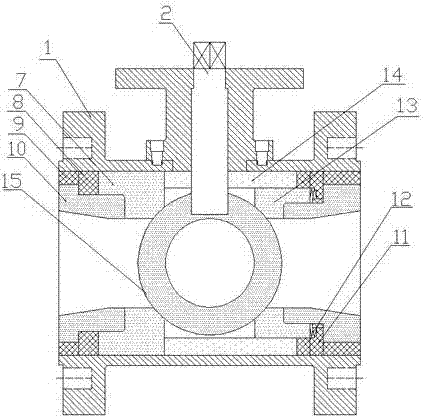
[0016] Embodiment 1, a kind of ceramic ball valve, refer to figure 1 , a ceramic ball 15 is installed in the housing 1, the valve stem 2 is fixedly connected with the ceramic ball 15, the left and right sides of the ceramic ball 15 are respectively provided with a left ceramic valve seat 7 and a right ceramic valve seat 13 in contact with it, The left ceramic valve seat 7 and the right ceramic valve seat 13 are positioned by the metal positioning ring 8. The outer surface of the left ceramic valve seat 7 is in close contact with the inner surface of the housing 1, and the outer surface of the right ceramic valve seat 13 is in close contact with the inner surface of the ceramic middle body 14. The side is in close contact, the other end of the ceramic middle body 14 is in close contact with the inside of the left ceramic valve seat 7, and the right side elevation of the right ceramic valve seat 13 and the ceramic flange lining 10 are provided with a disc spring pressure ring 11,...
Embodiment 2
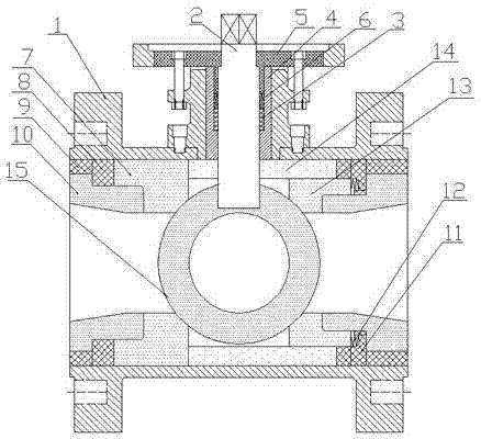
[0017] Embodiment 2, a kind of ceramic ball valve, refer to figure 2 , on the basis of Example 1, the inner side of the cavity where the valve stem 2 is installed is provided with an anti-corrosion sealing layer 4, and the anti-corrosion sealing layer 4 is made of high-performance materials such as tetrafluoro pads, zirconia ceramics, and Haci alloys, This embodiment adopts PTFE pads, etc. on the upper part of the anti-corrosion sealing layer 4. A groove is provided, and an O-ring 3 is installed in the groove, and a rubber pad 6 is arranged above the O-ring 3. The vertical part of the T-shaped pressure plate 5 The plate is divided into a circular body and extends into the installation valve rod 2 cavity to press the rubber pad 6. There is a gap between the horizontal plate part and the shell 1 and is connected by bolts. The shell 1 is an integrated structure, and the others are the same as in Example 1. exactly the same.
Embodiment 3
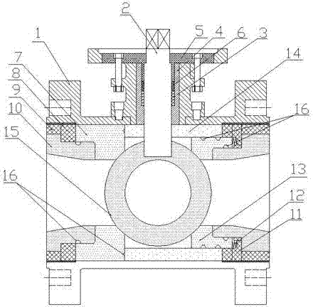
[0018] Embodiment 3, a kind of ceramic ball valve, refer to image 3 , is on the basis of embodiment 2, the flange lining metal ring 9, the left ceramic valve seat 7, the ceramic middle body 14 are threadedly connected with the inner side of the housing 1, the left ceramic valve seat 7, the right ceramic valve seat 13 and the ceramic method A sealing ring 16 is provided at the connecting portion of the blue inner lining 10 and the ceramic middle body 14, and the others are completely the same as in Embodiment 2.
PUM
 Abstract
Description
Claims
Application Information