Computational imaging method and imaging system based on nonplanar image sensor

An image sensor and imaging method technology, applied in the field of computational photography, can solve the problems of inability to effectively collect scene depth information, and achieve the effects of cost saving, accurate depth estimation results, and precise depth of field control

Active Publication Date: 2012-01-11
TSINGHUA UNIV
View PDF2 Cites 73 Cited by
  • Summary
  • Abstract
  • Description
  • Claims
  • Application Information

AI Technical Summary

Problems solved by technology

[0006] The purpose of the present invention is to provide a non-planar image sensor computational imaging method and system to solve the problem that traditional imaging cannot effectively collect scene dep

Method used


Image

  • Computational imaging method and imaging system based on nonplanar image sensor
  • Computational imaging method and imaging system based on nonplanar image sensor
  • Computational imaging method and imaging system based on nonplanar image sensor

Examples


Embodiment 1

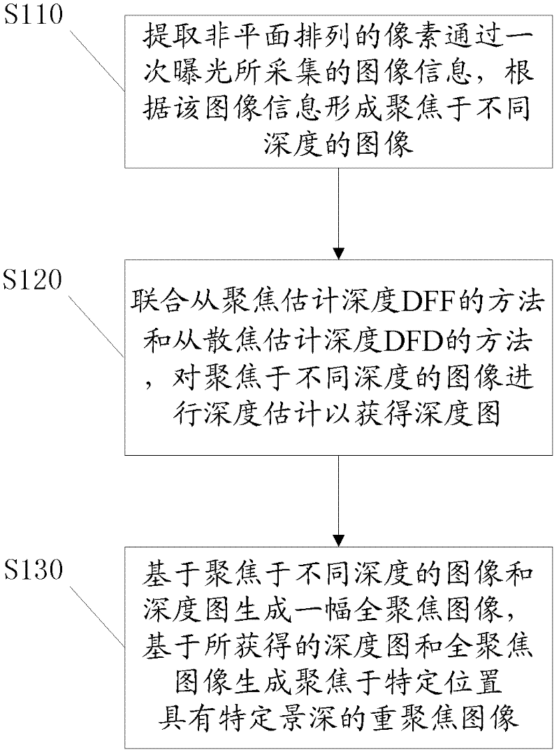
[0036] figure 1 It is a flowchart of a computational imaging method based on an image sensor according to Embodiment 1 of the present invention, combined below figure 1 Describe the steps of the method in detail.

[0037] Step S110, extracting the image information collected by the non-planar arrangement of the lighting surfaces, and forming images focused at different depths according to the image information.

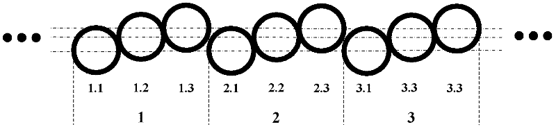
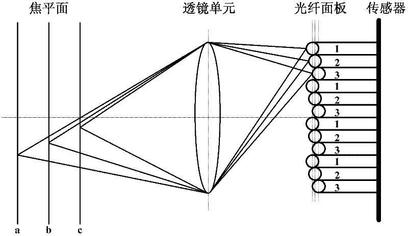
[0038] The image sensor involved in the computational imaging method of this embodiment adopts a non-planar lighting surface arrangement. In general, the lighting surface of the sensor is the sensor pixel. In order to obtain the imaging results of the scene under different focal planes in single-exposure acquisition, the pixel arrangement of the non-planar sensor surface is preferably divided into a specific number of height levels, and different The number of height levels corresponds to the number of different focal planes in the scene, and can also be determined ...

Embodiment 2

[0091] Figure 7 It is a schematic structural diagram of a computational imaging device according to Embodiment 2 of the present invention, combined with Figure 7 Describe in detail the composition of the computational imaging device.

[0092] The computational imaging device includes the following units:

[0093] image sensor unit , the surface of which is arranged in a non-planar manner, extracting image information collected by a single exposure on the surface arranged in a non-planar manner, and forming images focused at different depths according to the collected image information.

[0094] The surface of the image sensor unit adopts a non-planar arrangement. In general, the surface of the sensor is the pixel of the sensor. In order to obtain the imaging results of the scene under different focal planes in single-exposure acquisition, the pixel arrangement of the non-planar sensor surface is preferably divided into a specific number of height levels. Select The numb...


PUM


Abstract

The invention discloses a computational imaging method and an imaging system based on a nonplanar image sensor, and the light-receiving surface of the image sensor is arranged by adopting a nonplanar mode. The imaging method includes the following steps: extracting the image information which is acquired by the nonplanarly arranged light-receiving surface in single exposure, and generating an image focused at different depths according to the image information; in combination with the method for estimating depth from focus (DFF) and the method of estimating depth from defocus (DFD), carrying out depth estimation on the image focused at different depths to obtain a depth map; generating a full-focused image on the basis of the image focused at different depths and the depth map, and generating refocused images focused at specific positions and provided with specific depths of field on the basis of the obtained depth map and the full-focused image. The method and the system can use single exposure to effectively acquire the information of the depth of field, and can use a single image to restore and control the depth of field.

Description

technical field [0001] The present invention relates to the field of computational photography, in particular to the field of computational sensing, in particular to a computational imaging method and system for a non-planar image sensor. Background technique [0002] Traditional digital photography is essentially to obtain the projection of the scene in the three-dimensional world on the two-dimensional plane, and the obtained single image cannot accurately restore the depth and structure information of the three-dimensional scene, and cannot bring a sense of depth to the human eye. three-dimensional sense. The traditional camera imaging model needs to make a trade-off between the depth of field and the signal-to-noise ratio. The depth of field is adjusted by the aperture. When the aperture is larger, the depth of field is smaller. If you want to increase the signal-to-noise ratio, you need to take a long exposure, and the long exposure will introduce motion blur in the im...

Claims


Application Information

Patent Timeline
IPC IPC(8): G06T7/00H04N13/00
Inventor 戴琼海林星
Owner TSINGHUA UNIV
Why Eureka
Try Eureka