An ocean profile motion platform driven by ocean temperature difference and capable of depth control
A motion platform, temperature difference energy technology, applied in ocean energy power generation, accumulator device, mechanical power generation mechanism, etc., can solve the problems of difficult to achieve fixed depth control, long oil path, high pressure, etc.
- Summary
- Abstract
- Description
- Claims
- Application Information
AI Technical Summary
Problems solved by technology
Method used
Image
Examples
Embodiment 1
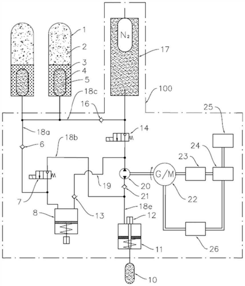
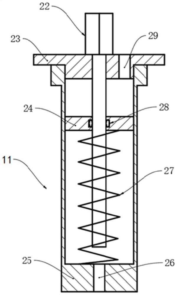
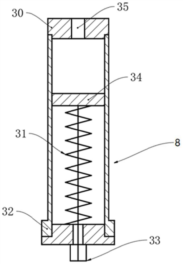
[0030] see Figure 1 to Figure 3 The cross-section motion platform of the present invention can work based on the ocean temperature difference, and specifically includes a sealed cavity 100, a buoyancy control circuit, a control unit, a power generation unit, and an electric storage unit for supplying electric energy to the buoyancy control circuit and the normal operation of the control unit. The electrical module is constructed with a rechargeable battery pack 24 of a lithium battery, and the rechargeable battery pack 24 is not only used to supply power to the control unit and the valves on the buoyancy control loop, but also to supply power to other loads 25 such as detection instruments; the buoyancy control loop Most of the structures, power generation unit, power storage unit and control unit are arranged in the sealed cavity 100 .
[0031] The power generation unit includes a hydraulic motor 20 and a generator 22, wherein the hydraulic motor 20 can be used as a motor an...
Embodiment 2
[0066] As a description of Embodiment 2 of the present invention, only the differences from Embodiment 1 above will be described below, that is, the structure of the liquid storage pump will be mainly described.
[0067] see Figure 4 , the liquid storage pump 1 includes a phase change cavity 40, the inner cavity of the phase change cavity 40 is separated by a third piston 45 into a phase change material cavity at the upper part and a third hydraulic oil cavity at the lower part, and the third piston 45 is in close contact with The inner wall surface of the phase change cavity 40 has good sealing and lubrication; the phase change material cavity is used to store the phase change material 41, the third hydraulic oil cavity is used to store the hydraulic oil 42, and the third hydraulic oil cavity is provided with a The third piston 45 is driven to compress the third compression spring 44 of the phase change material chamber, and the third hydraulic oil chamber is connected to th...
Embodiment 3
[0069] As the description of Embodiment 3 of the present invention, only the differences from Embodiment 1 above will be described below, that is, the structure of the liquid storage pump will be mainly described.
[0070] see Figure 5 , the outer hydraulic cylinder includes a cylinder body 27, a sealing device 28, a lower end cover 29, a first piston 32 and an upper end cover 33; the inner chamber of the cylinder body 27 is divided into a first hydraulic oil chamber and a water suction chamber by the first piston 32, and the water suction chamber There is a first compression spring 30 for driving the first piston 32 to compress the first hydraulic oil chamber, and a metal bellows 31 is set in the water suction chamber, and the water inlet port of the metal bellows 31 is watertightly set in the water suction chamber Inside the water suction port, the first compression spring 30 is set outside the metal bellows 31; inside the outer hydraulic cylinder is installed a first cable...
PUM
 Abstract
Description
Claims
Application Information
 - R&D
- Intellectual Property
- Life Sciences
- Materials
- Tech Scout
- Unparalleled Data Quality
- Higher Quality Content
- 60% Fewer Hallucinations
Browse by: Latest US Patents, China's latest patents, Technical Efficacy Thesaurus, Application Domain, Technology Topic, Popular Technical Reports.
© 2025 PatSnap. All rights reserved.Legal|Privacy policy|Modern Slavery Act Transparency Statement|Sitemap|About US| Contact US: help@patsnap.com


