Supercharge Your Innovation With Domain-Expert AI Agents!

Electric connector

A technology of electrical connectors and connecting parts, which is applied in the direction of connection, fixed connection, two-component connection device, etc., and can solve the problem of crosstalk easily generated by signal terminals

Inactive Publication Date: 2012-01-11
TYCO ELECTRONICS (SHANGHAI) CO LTD +1
View PDF6 Cites 12 Cited by
  • Summary
  • Abstract
  • Description
  • Claims
  • Application Information

AI Technical Summary

Problems solved by technology

like Figure 9 As shown, the welding parts 818, 817, 927, 928, 929, 817, 818 of all terminals of the USB3.0 are arranged in a row along the horizontal direction, resulting in a The distance between them is small, which leads to crosstalk easily between the signal terminals in the terminal groups 811, 812, 813 and the terminal groups 920, 281, 923

Method used


Image

  • Electric connector
  • Electric connector
  • Electric connector

Examples


Embodiment Construction

[0032] The technical solution of the present invention will be further specifically described below through the embodiments and in conjunction with the accompanying drawings. In the specification, the same or similar reference numerals designate the same or similar components. The following description of the embodiments of the present invention with reference to the accompanying drawings is intended to explain the general inventive concept of the present invention, but should not be construed as a limitation of the present invention.

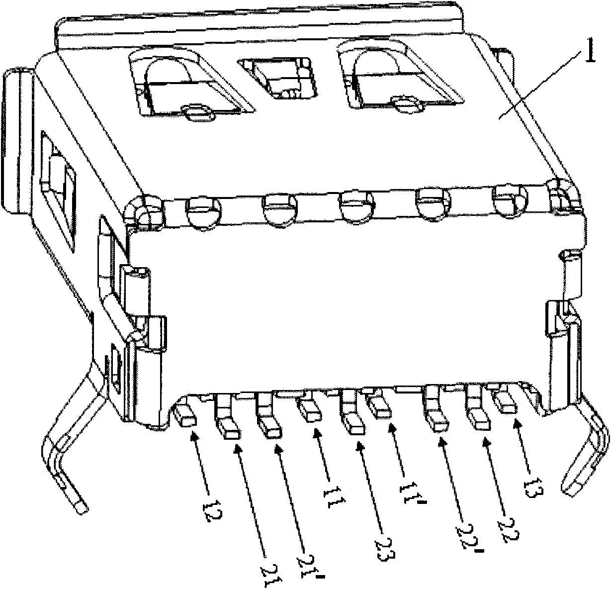
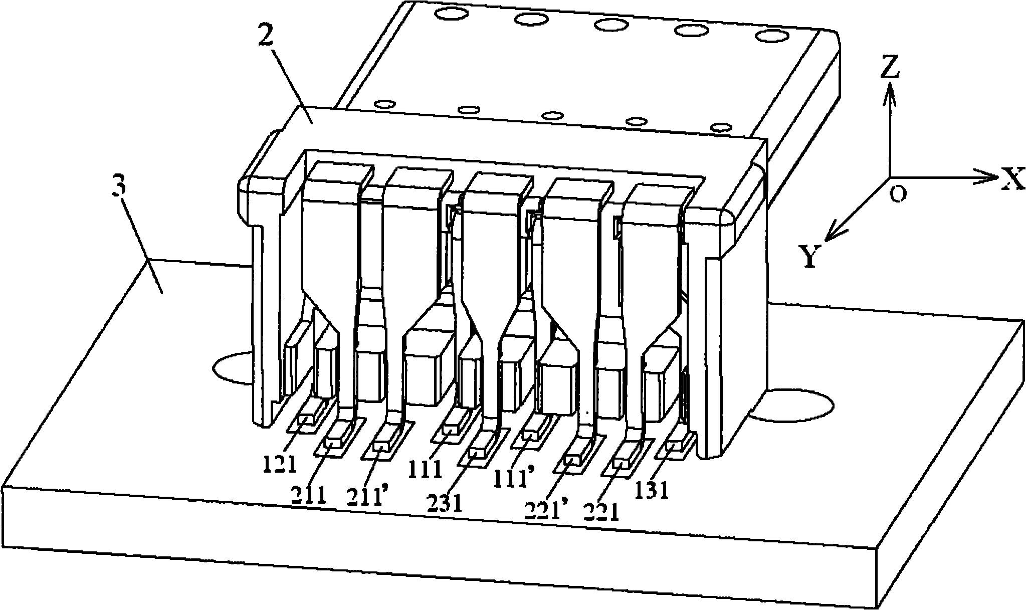
[0033] figure 1 A three-dimensional schematic view of an electrical connector according to an embodiment of the present invention is shown. figure 2 show figure 1 A three-dimensional schematic diagram of the electrical connector soldered to the circuit board, where the shielding shell is not shown in the figure.

[0034] exist figure 1 with figure 2 In the present invention, a USB3.0 connector is taken as an example to explain and ill...


PUM


Abstract

The invention discloses an electric connector, which comprises an insulation main body, a plurality of first terminals and a plurality of second terminals, wherein the insulation main body has a transverse direction and a longitudinal direction; the plurality of first terminals are held in the insulation main body, and each first terminal comprises a first contact part, a first welding part and a first connecting part, wherein the first welding part is used for welding with the surface of a circuit board, and the first connecting part is longitudinally connected with the first contact part and the first welding part; and the plurality of second terminals are held in the insulation main body, and each second terminal comprises a second contact part, a second welding part and a second connecting part, wherein the second welding part is used for welding with the surface of the circuit board, and the second connecting part is longitudinally connected with the second contact part and the second welding part. In the invention, the first welding parts of the plurality of first terminals and the second welding parts of the plurality of second terminals are arrayed to form two different lines rather than regularly arrayed to form one line, and therefore a space between the first welding parts and the second welding parts is increased, and mutual crosstalk between the first terminals and the second terminals is consequently reduced.

Description

technical field [0001] The invention relates to an electrical connector, in particular to an electrical connector capable of transmitting high-speed signals. Background technique [0002] Electrical connectors use conductive terminals to provide signal connections between electronic devices. Usually, the spacing between the conductive terminals is very close, so that crosstalk occurs between adjacent conductive terminals, thereby destroying the integrity of the signal. [0003] Universal Serial Bus (USB) is a universal serial bus standard protocol. The standard association has now begun to upgrade the standard from the now popular USB2.0 standard protocol to USB3.0 standard protocol, and the signal transmission speed has changed from the original 480Mbit The theoretical upper limit of / s is increased by 10 times to 5Gbit / s. Correspondingly, this poses a greater challenge to the design of USB connectors, especially how to reduce the crosstalk between adjacent signal conductiv...

Claims


Application Information

Patent Timeline
IPC IPC(8): H01R12/57
CPCH01R13/6461H01R24/60
Inventor 拉皮多特·多伦李志强李慧斌
Owner TYCO ELECTRONICS (SHANGHAI) CO LTD
Features
  • R&D
  • Intellectual Property
  • Life Sciences
  • Materials
  • Tech Scout
  • Unparalleled Data Quality
  • Higher Quality Content
  • 60% Fewer Hallucinations
Learn More