Supercharge Your Innovation With Domain-Expert AI Agents!

Overvoltage circuit, and motor starter, overload relay and low-power system including the same

A technology of overvoltage and relay, applied in the fields of overload relay or low power system, voltage clamping circuit, motor starter, which can solve high cost and other problems

Inactive Publication Date: 2012-01-11
EATON CORP
View PDF8 Cites 2 Cited by
  • Summary
  • Abstract
  • Description
  • Claims
  • Application Information

AI Technical Summary

Problems solved by technology

However, it is believed that such programmable MOSFETs have relatively high cost

Method used


Image

  • Overvoltage circuit, and motor starter, overload relay and low-power system including the same
  • Overvoltage circuit, and motor starter, overload relay and low-power system including the same
  • Overvoltage circuit, and motor starter, overload relay and low-power system including the same

Examples


example 1

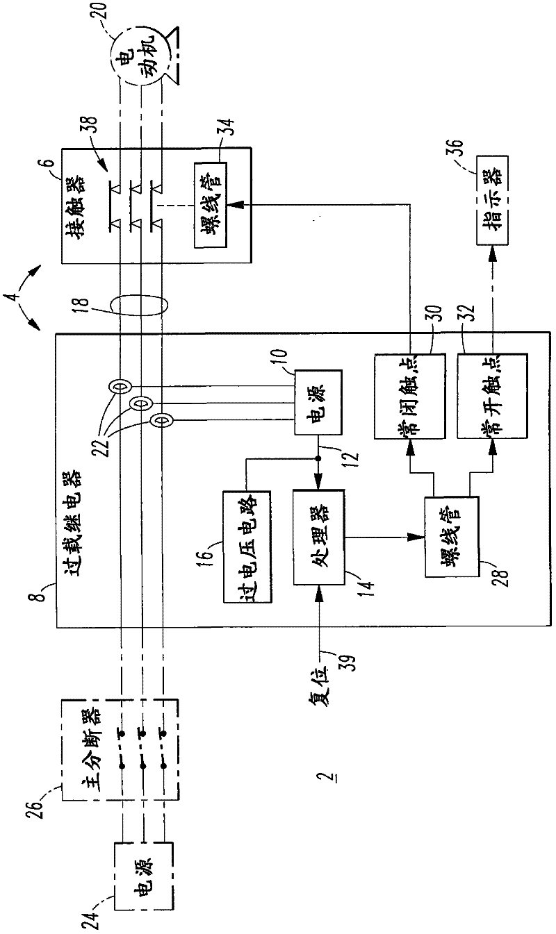
[0033] Preferably, the power supply 10 of the overload relay 8 is configured to be parasitically powered by several power lines 18 to the electric motor 20 (shown in phantom line drawing). In that case, the overload relay 8 also includes several current transformers 22 configured to detect the current flowing to the motor 20 and to supply power to the power source 10 .

[0034] The exemplary motor starter system 2 also includes a power source 24 (shown in phantom line drawing) and a main disconnect 26 (shown in phantom line drawing), which supplies power to overload relay 8 .

[0035] The exemplary processor 14 controls a solenoid 28 which in turn controls a normally closed contact 30 and a normally open contact 32 . An exemplary normally closed contact 30 controls a solenoid 34 of the contactor 6 . Exemplary normally open contacts 32 control a display 36 that shows the status of separable contacts 38 of contactor 6 . The exemplary processor 14 may also input a reset signal ...

example 2

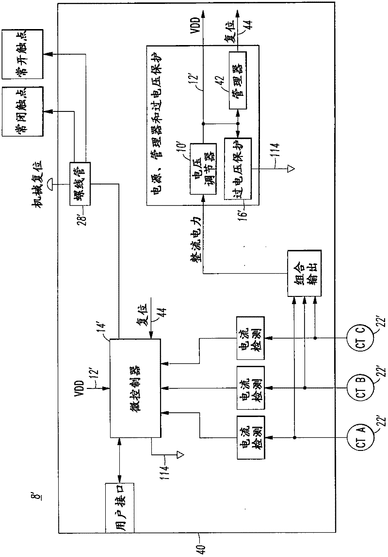
[0037] figure 2 shows that it can be used with figure 1 The overload relay 8 is the same as or similar to the overload relay 8'. The overload relay 8' similarly includes: a power supply 10' having a voltage 12' (such as, but not limited to, +2.5V); a microcontroller 14' (such as, but not limited to, a ); overvoltage protection circuit 16'; solenoid 28'.

[0038] The disclosed solid state overload relay 8' is a parasitic powered motor protection device. The current transformer 22' is used to transfer the current from the current to the motor (not shown, but see figure 1 The electromagnetic field generated by the alternating current (AC) of the electric motor 20) is converted into electric power for the solid-state overload relay 8'. As such, the corresponding control circuit 40 can operate on relatively little power (eg, but not limited to, approximately 1.5 mW). By significantly reducing the amount of power required to operate the control circuit 40, the size of the curr...

example 3

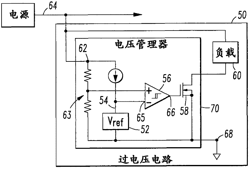
[0041] image 3 shows the overvoltage circuit 50, which can be used with figure 1 and2 The overvoltage circuits 16, 16' are the same or similar. The overvoltage circuit 50 includes a voltage reference 52 having a voltage 54 , a comparator 56 , a switch 58 and a load 60 . The comparator 56 includes: a first input 62 for the supply voltage 64 to be protected; a second input 65 (−) for the voltage reference voltage 54 ; and an output 66 . In this example, the input 62 includes a voltage divider 63 that cooperates with the voltage 54 of the voltage reference 52 to determine the threshold voltage. And, in this example, voltage 54 is less than the threshold voltage. Switch 58 is controlled by comparator output 66 and is configured to electrically connect supply voltage 64 through load 60 to ground 68 whenever supply voltage 64 exceeds a threshold voltage.


PUM


Abstract

The invention relates to an overvoltage circuit, and a motor starter, an overload relay and a low-power system including the same. The motor starter (4) includes a contactor (6) and an overload relay (8). The overload relay includes a power supply (10) having a voltage (12;64), a processor (14) powered by the power supply voltage and being structured to control the contactor, and an overvoltage circuit (16;50). The overvoltage circuit includes a voltage reference (52) having a voltage (54), a comparator (56), a load (60) and a switch (58). The comparator includes a first input (62) for the power supply voltage, the first input cooperating with the voltage of the voltage reference to determine a threshold voltage, a second input (65) for voltage reference voltage, and an output (60). The switch is controlled by the comparator output and is structured to electrically connect the power supply voltage to ground (68) through the load whenever the power supply voltage exceeds the threshold voltage.

Description

technical field [0001] The disclosed concept relates generally to overvoltage circuits, and in particular to voltage clamping circuits for DC power supplies, such as those used in processors. The disclosed concept also relates to motor starters, overload relays or low power systems using these circuits. Background technique [0002] It is known to use Zener diodes as a relatively low cost voltage clamping circuit. However, Zener diodes exhibit non-ideal characteristics, eg, conduct a certain amount of current before reaching the rated Zener voltage. For very small power systems, this current draw under nominal operating conditions may be unacceptably high. [0003] US Patent No. 5436552 discloses a clamping circuit for clamping a reference voltage at a predetermined level. The clamp circuit includes a constant current circuit with a constant current source and a current mirror circuit. The trimmable resistor receives a constant current from the constant current circuit, ...

Claims


Application Information

Patent Timeline
Patent Type & Authority Applications(China)
IPC IPC(8): H02H9/04H02H7/085H02H3/08H02P1/26H02M1/32
CPCH02H9/04H02H3/08H02H1/063H02H9/041G05F1/575G05F1/66
Inventor J·D·赖利
Owner EATON CORP
Features
  • R&D
  • Intellectual Property
  • Life Sciences
  • Materials
  • Tech Scout
  • Unparalleled Data Quality
  • Higher Quality Content
  • 60% Fewer Hallucinations
Learn More