Image display system and image display method

An image display and image technology, applied in image communication, closed-circuit television system, traffic control system, etc.

Inactive Publication Date: 2012-01-11
FUJITSU GENERAL LTD
View PDF7 Cites 14 Cited by
  • Summary
  • Abstract
  • Description
  • Claims
  • Application Information

AI Technical Summary

Problems solved by technology

In addition, if the light intensity of the lighting is increased uniformly, a very large amount of power is required to widen the area to be illuminated, so the power consumption will be high.

Method used


Image

  • Image display system and image display method
  • Image display system and image display method
  • Image display system and image display method

Examples


no. 1 Embodiment approach

[0082]

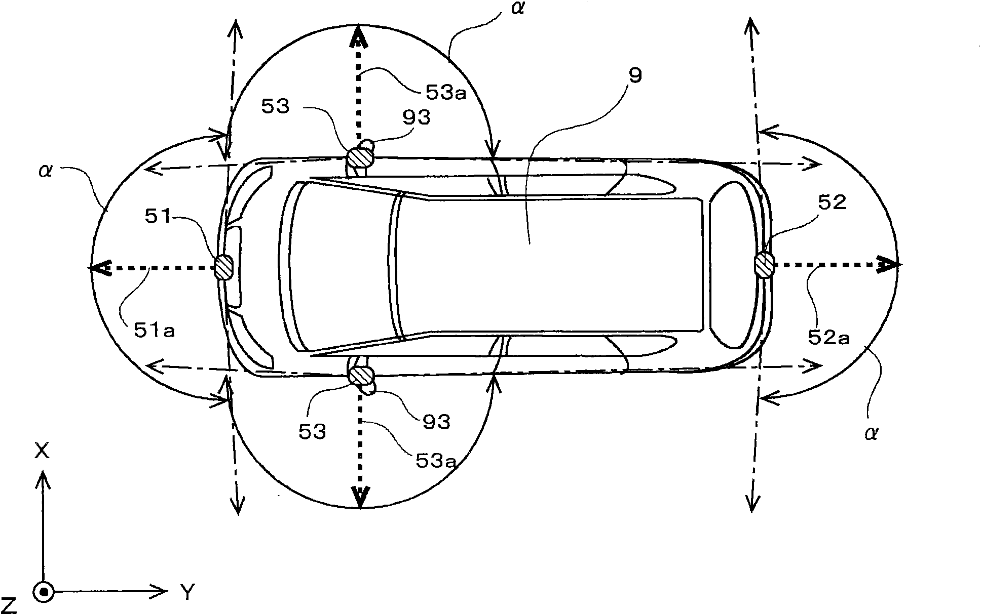
[0083] figure 1 It is a block diagram showing the configuration of the image display system 120 of the first embodiment. This image display system 120 is mounted on a vehicle (an automobile in this embodiment), and has a function of capturing images of the surroundings of the vehicle and generating an image to display inside the vehicle. A user of the image display system 120 (typically, a driver) can grasp the situation around the vehicle in real time by utilizing the image display system 120 .

[0084] Such as figure 1 As shown, the image display system 120 mainly includes an image processing device 100 that generates a vehicle peripheral image showing the vehicle peripheral situation, and a navigation device 20 that displays various information to a user riding in the vehicle. The vehicle peripheral image generated by the image processing device 100 is displayed on the navigation device 20 .

[0085] The navigation device 20 provides navigation guidance to the...

no. 2 Embodiment approach

[0192]

[0193] Next, a second embodiment will be described. In the first embodiment, a common light quantity parameter that does not relate to the type of vehicle surrounding image to be displayed is used, but in the second embodiment, a light quantity parameter corresponding to the type of vehicle surrounding image is used. Since the configuration and operation of the image display system 120 of this embodiment are basically the same as those of the first embodiment, only the differences from the first embodiment will be described below.

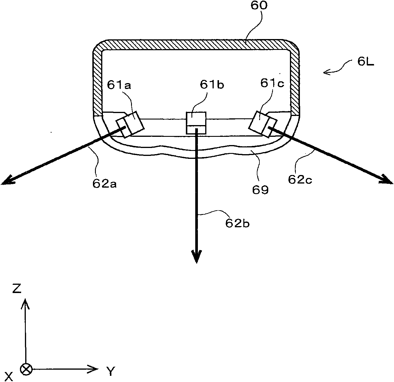
[0194] Figure 18 It is a figure which shows the example of the light quantity setting data 4b of 2nd Embodiment. As described above, there are six light quantity parameters corresponding to the front light source 61a, center light source 61b, and rear light source 61c of the left lighting unit 6L, and the front light source 61d, center light source 61e, and rear light source 61f of the right lighting unit 6R. In the present embodiment...

no. 3 Embodiment approach

[0224] Next, a third embodiment will be described. In the second embodiment, all light quantity parameters can be changed. In contrast, in the third embodiment, a part of the light quantity parameters cannot be changed for a specific type of vehicle surrounding image among a plurality of types of vehicle surrounding images. Since the configuration and operation of the image display system 120 of this embodiment are basically the same as those of the second embodiment, differences from the second embodiment will be described below.

[0225] Figure 26 It is a figure which shows the example of the light quantity setting data 4b of 3rd Embodiment. Such as Figure 26 As shown, in the parameter group St corresponding to the side image P23, "0 is fixed" is displayed for the light quantity parameters of the rear light sources 61c and 61f.

[0226] The rear area BA illuminated by the rear light sources 61c and 61f (see Figure 4 ), are not included in the side image P23 as the subj...


PUM


Abstract

The present invention provides an image display system and an image display method. An image display system (120) includes a plurality of light sources respectively illuminating a plurality of divided regions. A user can change each of a plurality of light-amount parameters respectively specifying an amount of light to be output by each of the plurality of light sources (61a-61f) by an operation on a change screen (21a). Therefore, the user can illuminate each of the plurality of divided regions with an amount of light that he / she desires. As a result, the user can illuminate and definitely identify a subject difficult for the user to see and a subject to which the user needs to pay attention.

Description

technical field [0001] The present invention relates to a technique for displaying an image showing a situation around a vehicle. Background technique [0002] Conventionally, a known image display system is mounted on a vehicle such as an automobile, and displays an image of the surrounding area of ​​the vehicle captured by an on-vehicle camera on a display inside the vehicle. By using this image display system, the driver can grasp the surrounding situation of the vehicle substantially in real time. [0003] For example, the outer area of ​​the front fender on the opposite side of the driver's seat tends to become a blind spot when viewed from the driver's seat, and it is difficult for the driver to grasp the clearance between the vehicle body and obstacles. On the other hand, if an image display system is used, an image showing the outer area of ​​the front fender can be obtained by taking pictures of the vehicle-mounted camera, and the image can be displayed on a monito...

Claims


Application Information

Patent Timeline
Patent Type & Authority Applications(China)
IPC IPC(8): H04N7/18G08B21/00
CPCH04N7/181G08G1/167
Inventor 谷口奖山田正博
Owner FUJITSU GENERAL LTD
Why Eureka
Try Eureka