
Vehicular lighting device

A technology for lamps and vehicles, applied in the direction of headlights, road vehicles, vehicle parts, etc., can solve the problems of illumination width limitation, pedestrian glare, etc., and achieve the effect of improving response

Active Publication Date: 2020-12-01
KOITO MFG CO LTD
View PDF12 Cites 0 Cited by
  • Summary
  • Abstract
  • Description
  • Claims
  • Application Information

AI Technical Summary

Problems solved by technology

Therefore, compared with the low beam, the high beam has higher visibility and can be seen more easily by the driver, but there is a problem that it may affect the driver of the vehicle in front or the pedestrian belt existing in front of the vehicle. to glare
In the LED array method, two or more non-illuminated areas can be set, but these non-illuminated areas may be discrete areas, because the width of each non-illuminated area is limited by the illuminated width of the LED chip

Method used


Image

  • Vehicular lighting device
  • Vehicular lighting device
  • Vehicular lighting device

Examples


Embodiment Construction

[0022] A preferred embodiment of the present invention will be described with reference to the accompanying drawings. The same or equivalent constituent elements, members, and processing steps shown in the drawings are given the same reference numerals or signs, and description of these elements and other elements will not be repeated. This embodiment is not intended to limit the present invention but is merely exemplary, and all features and combinations thereof described in this embodiment are not necessarily essential to the present invention.

[0023] In this specification, "the state where member A is connected to member B" refers not only to the case where member A and member B are physically directly connected to each other, but also refers to a state in which member A and member B are not connected via electrical connections to these members A, B. A case where other components that substantially affect or do not impair the functions and effects provided by the coupling...


PUM


Abstract

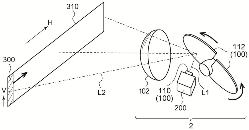
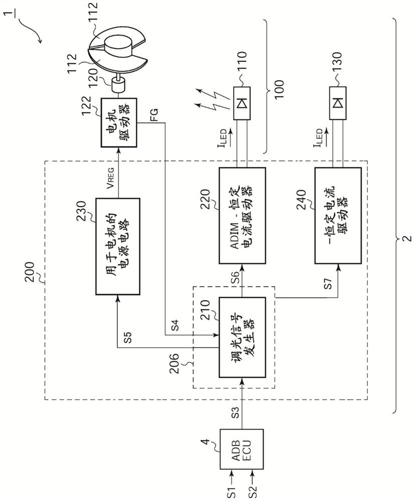
A vehicular lamp (2) is provided with a scanning-type light source (100) that includes a semiconductor light source and a motor (120), and scans a region in front of the lamp with light emitted from the semiconductor light source in accordance with the movement of the motor (120); and a lighting circuit (200) that changes the amount of light of the semiconductor light source in synchronization with the movement of the motor (120) during a normal lighting period so as to obtain a predetermined light distribution pattern. The lighting circuit (200) starts a movement of the motor (120) in response to a lighting command for headlamp flickering during a stop period of the motor (120), and continuously lights the semiconductor light source asynchronously with the movement of the motor (120) during a start period prior to the normal lighting period.

Description

technical field [0001] The present invention relates to vehicle lamps used in automobiles and the like. Background technique [0002] Luminaires for vehicles are generally capable of switching between a low beam mode and a high beam mode. The low beam is suitable for illuminating the area near the vehicle with a predetermined illuminance, and stipulates that the light intensity distribution will not cause glare to the oncoming vehicle (oncoming vehicle) or the vehicle in front. Low beams are mainly used when the vehicle is driving in town or urban areas. On the other hand, high beams are suitable for illuminating a wide range or a distant area in front of the vehicle with relatively high illuminance, and are mainly used when the vehicle is traveling at high speed on a road with a small number of oncoming and preceding vehicles. Therefore, compared with the low beam, the high beam has higher visibility and can be seen more easily by the driver, but there is a problem that i...

Claims


Application Information

Patent Timeline
Patent Type & Authority Applications(China)
IPC IPC(8): F21S41/675B60Q1/14B60Q1/076F21Y115/30F21Y115/20F21W107/10F21W102/13
CPCF21S41/675B60Q1/076B60Q1/1415F21W2102/13F21W2107/10F21Y2115/30F21Y2115/20F21S41/16F21S41/147F21S41/255F21S41/663Y02B20/40F21S41/14F21S41/32F21S41/25F21Y2115/00F21V23/003
Inventor 村上健太郎上杉笃志
Owner KOITO MFG CO LTD
Learn More