
Test probe device

A test probe and test pin technology, applied in the direction of measuring devices, using optical devices, measuring electricity, etc., can solve the problems of uncontrollable contact resistance, unable to guarantee the same contact resistance, and pits left on the test panel.

Active Publication Date: 2014-01-15
SHENZHEN MASONE ELECTRONICS
View PDF5 Cites 9 Cited by
  • Summary
  • Abstract
  • Description
  • Claims
  • Application Information

AI Technical Summary

Problems solved by technology

[0003] The purpose of the embodiments of the present invention is to provide a test probe device, aiming at solving the problems in the prior art that the contact resistance cannot be controlled, the contact resistance of each test cannot be guaranteed to be the same, and pits are left on the test panel

Method used


Image

  • Test probe device
  • Test probe device
  • Test probe device

Examples


Embodiment Construction

[0014] In order to make the object, technical solution and advantages of the present invention clearer, the present invention will be further described in detail below in conjunction with the accompanying drawings and embodiments. It should be understood that the specific embodiments described here are only used to explain the present invention, not to limit the present invention.

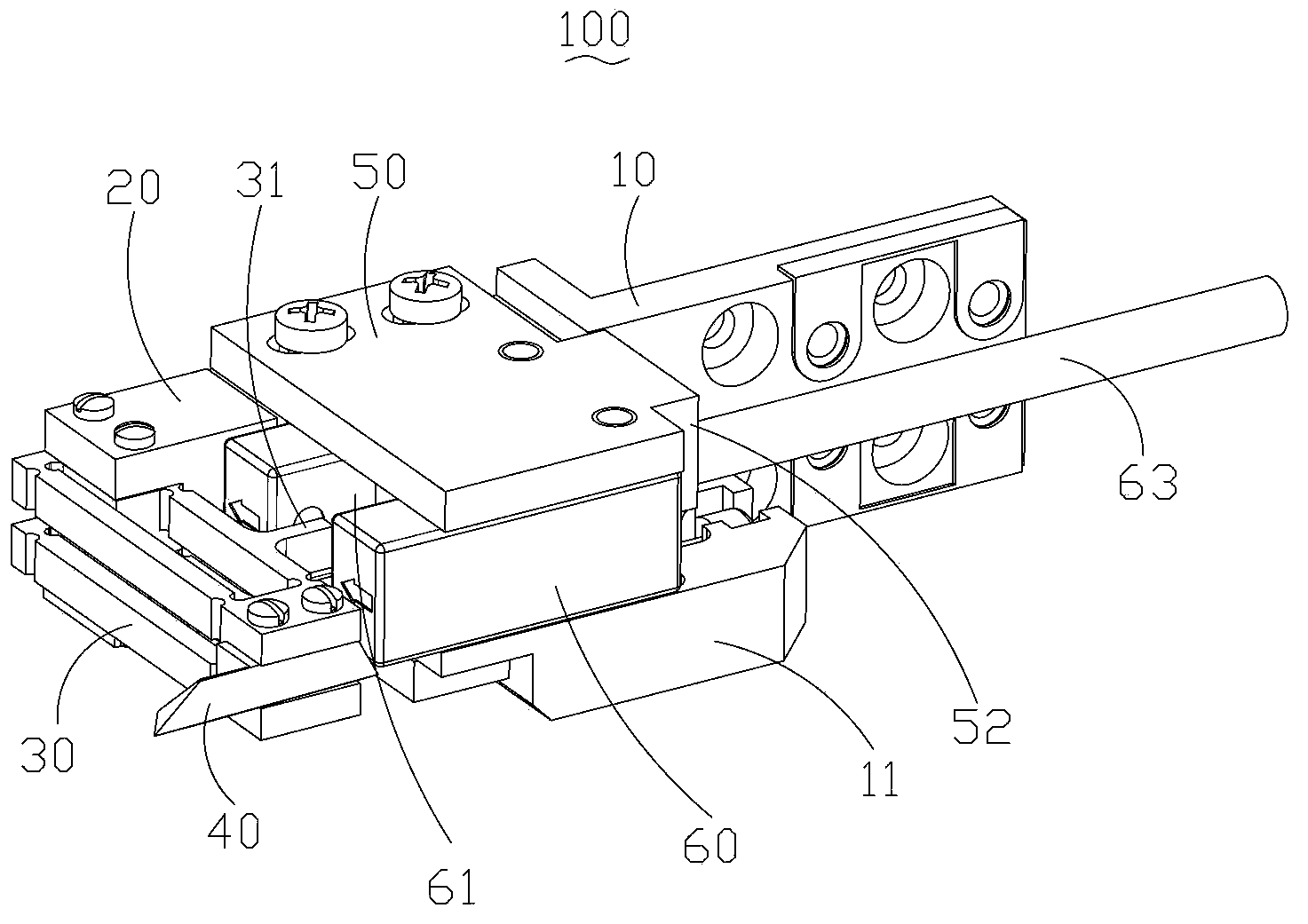
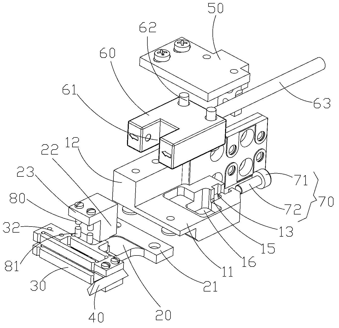
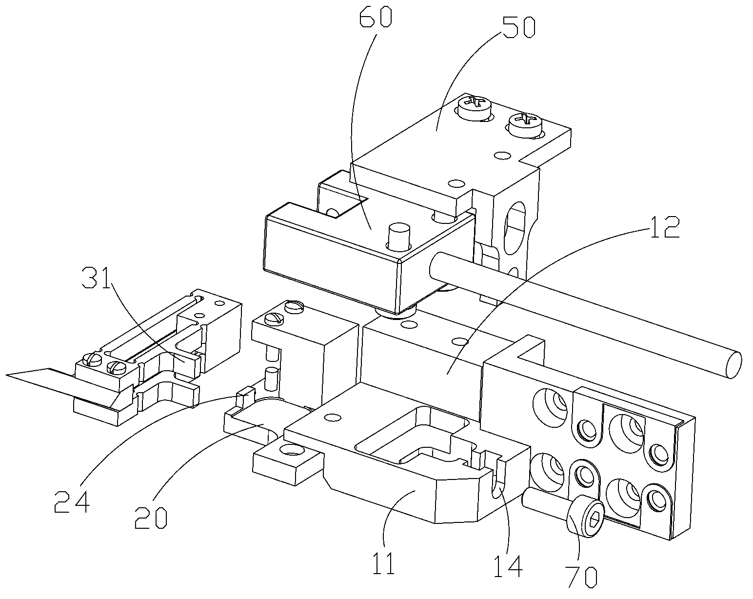
[0015] see Figure 1 to Figure 5 , the test probe device 100 provided by the first embodiment of the present invention is used in a flying probe test machine. The test probe device 100 includes a main body seat 10, a bracket fixing seat 20 installed at one end of the main body seat 10, an elastic bracket 30 whose one end is fixed on the bracket fixing seat 20, and an elastic bracket 30 fixed on the elastic bracket 30. The test needle 40 at one end, the sensor adjustment seat 50 fixed relative to the main body seat 10 after moving in the moving direction of the test needle 40, moves with the sensor...


PUM


Abstract

The invention provides a test probe device which comprises a main body seat, a sensor adjusting seat, a displacement sensor, a bracket fixing seat, an elastic bracket, a test pin and an adjusting piece. The displacement sensor is installed on the sensor adjusting seat, the sensor adjusting seat is installed on the main body seat, and the front-and-back position of the displacement sensor can be adjusted by the adjusting piece. The test pin is installed on the elastic bracket, the elastic bracket is fixed on the bracket fixing seat, and the bracket fixing seat is connected with the main body seat. Resistance of the device is calibrated and the relationship between the magnitude of contact force and the backward displacement of the test pin of the device is tested so as to acquire the amount of displacement under an appropriate resistance and the relationship between the contact force and the amount of displacement of the test pin. The elastic bracket has a light shading block, the amount of displacement of the test pin is tested through the amount of through light, shaded by the light shading block, of the displacement sensor, contact resistance and contact force can be controlled to be within a proper value, and the test accuracy and the surface quality of a test panel are ensured.

Description

technical field [0001] The invention belongs to a printed circuit board (PCB) test device, in particular to a test probe device used for a flying probe test machine. Background technique [0002] The flying probe tester is a system for testing printed circuit boards (PCBs), and the flying probe test is one of the methods to check the electrical function of the PCB (open and short circuit test). The flying probe testing machine moves each test pin to a fixed unit to be tested, and the test pin contacts the pads and via holes of the test PCB board, thereby testing a single component of the unit under test. The test accuracy of the flying probe tester is largely affected by the contact resistance generated after the test needle contacts the test panel, but the contact resistance cannot be eliminated. The test probe device of the existing flying probe testing machine cannot control the contact resistance, nor can it ensure that the contact resistance of each test is the same, a...

Claims


Application Information

Patent Timeline
Patent Type & Authority Applications(China)
IPC IPC(8): G01R1/067G01B11/02
Inventor 谭艳萍黄俊华廉成宋福民高云峰
Owner SHENZHEN MASONE ELECTRONICS
Learn More