Eureka AIR delivers breakthrough ideas for toughest innovation challenges, trusted by R&D personnel around the world.

Pipe rotating device

A pipe material and driving device technology, which is applied in the direction of quenching device, heat treatment equipment, furnace, etc., can solve the problems of low degree of automation, high labor intensity of workers, uneven quenching at the end of pipe material, etc., achieve high degree of automation and reduce labor costs. The effect of labor intensity and reasonable structure

Inactive Publication Date: 2012-01-18
WUXI HUALIAN SCI & TECH GROUP
View PDF4 Cites 0 Cited by
  • Summary
  • Abstract
  • Description
  • Claims
  • Application Information

AI Technical Summary

Problems solved by technology

[0002] In the prior art, the quenching of the end of the oil drilling pipe is usually carried out by fixing the pipe material or manually rotating the pipe material. In this way, the quenching of the end of the pipe material is uneven, the labor intensity of the workers is high, and the degree of automation is extremely low.

Method used


Image

  • Pipe rotating device
  • Pipe rotating device
  • Pipe rotating device

Examples


Embodiment Construction

[0009] The present invention will be further described below in conjunction with specific drawings and embodiments.

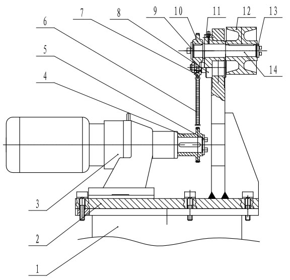
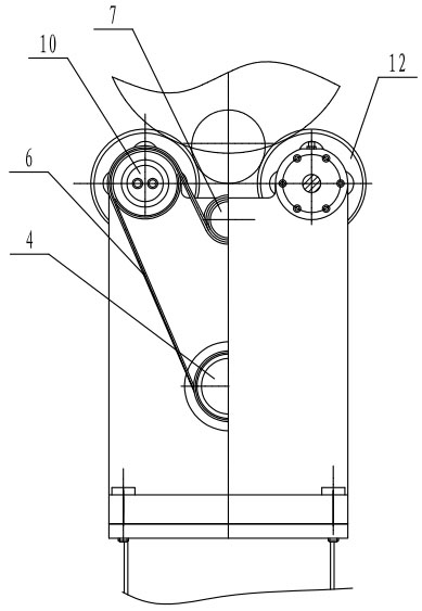
[0010] like Figure 1 to Figure 2 Shown: the present invention mainly consists of base 1, bracket 2, reducer 3, driving sprocket 4, main cover plate 5, chain 6, transition sprocket 7, transition sprocket shaft 8, front axle cover 9, driven sprocket 10, Sliding sleeve 11, drive roller 12, rear axle cover 13, drive shaft 14 etc. constitute.

[0011] The present invention adopts support 2 to be installed on the base 1, and the driving sprocket 4 is fixed on the reducer 3 through the main cover plate 5, the reducer 3 is installed on the support 2, the transition sprocket shaft 8 is installed on the support 2, and the transition sprocket 7 The bearing is mounted on the end of the transition sprocket shaft 8, the sliding sleeve 11 is installed on the bracket 2, the driving shaft 14 passes through the sliding sleeve 11, the driven sprocket 10 and the driving roller 1...


PUM


Abstract

The invention relates to a pipe driving device. A pipe is carried by two transmission rollers which are positioned at the same horizontal height and are a certain distance away from each other and is driven thereby to rotate; one end of a central shaft of each transmission roller is provided with a driven chain wheel; a transition chain wheel is arranged between two driven chain wheels; a driving chain wheel is connected to an output shaft of a driving motor; and a chain passes through the driving chain wheel, the first driven chain wheel, the transition chain wheel, the second driven chain wheel in sequence to form a driving chain. In the device, the two transmission rollers are connected together by a speed reducer through the chain and the transition chain wheel, so that the two transmission rollers are guaranteed to synchronously rotate, the stability of the pipe during rotation is guaranteed, and automatic rotation quenching work of the pipe is finished; the labor intensity of workers can be greatly reduced; and the device has high degree of automation, a rational structure and high working efficiency.

Description

technical field [0001] The invention relates to pipe material processing equipment, in particular to a pipe material rotating device. Background technique [0002] In the prior art, the quenching of the end of the oil drilling pipe is mostly carried out by fixing the pipe material or manually rotating the pipe material. In this way, the quenching of the pipe material end is uneven, the labor intensity of the workers is high, and the degree of automation is extremely low. Contents of the invention [0003] The object of the present invention is to overcome the deficiencies in the prior art, and provide a pipe material rotating device, which connects two rotating rollers together by a reducer through a chain and a transition sprocket, so as to ensure that the two rotating rollers rotate synchronously, ensuring The pipe material is stable during the rotation process, and the automatic rotation quenching operation of the pipe material is completed. [0004] The technical sche...

Claims


Application Information

Patent Timeline
IPC IPC(8): C21D1/62C21D9/08
Inventor 吴云强杨念记方长海周军记张盛吴信保
Owner WUXI HUALIAN SCI & TECH GROUP
Why Eureka
Eureka Blog
Learn More