Radial decoupling taper magnetic bearing with three degree of freedom

A degree of freedom, magnetic bearing technology, applied in the directions of bearings, shafts and bearings, mechanical equipment, etc., can solve the problems of large torsional negative torque, reduced bearing capacity of load-bearing channels, and reduced excitation, and achieve small torsional negative torque and maximum bearing capacity. The effect of large and increasing output

Inactive Publication Date: 2013-03-20
BEIHANG UNIV
View PDF2 Cites 0 Cited by
  • Summary
  • Abstract
  • Description
  • Claims
  • Application Information

AI Technical Summary

Problems solved by technology

At the same time, the stator part of the existing radial magnetic bearing is generally divided into four magnetic poles, and the permanent magnet magnetic circuit and the electric excitation magnetic circuit are mutually coupled between each magnetic pole, such as the permanent magnet bias outer rotor radial magnetic The bearing and the permanent magnet bias outer rotor radial hybrid magnetic bearing with redundant structure in the patent 200710063272.6 all include four mutually coupled radial magnetic poles. , the size of the air gap under the four radial magnetic poles is no longer equal. If a channel in the radial direction is loaded with current, affected by channel coupling, the current will generate an additional force in the other channel, while the excitation of the channel itself will decrease. , so that the bearing capacity of the load-bearing channel is reduced
Due to the above defects, the existing magnetic bearings have the disadvantages of large torsional negative torque and serious radial channel coupling in the application of large-angle torsional magnetic levitation reaction flywheels

Method used


Image

  • Radial decoupling taper magnetic bearing with three degree of freedom
  • Radial decoupling taper magnetic bearing with three degree of freedom
  • Radial decoupling taper magnetic bearing with three degree of freedom

Examples


Embodiment Construction

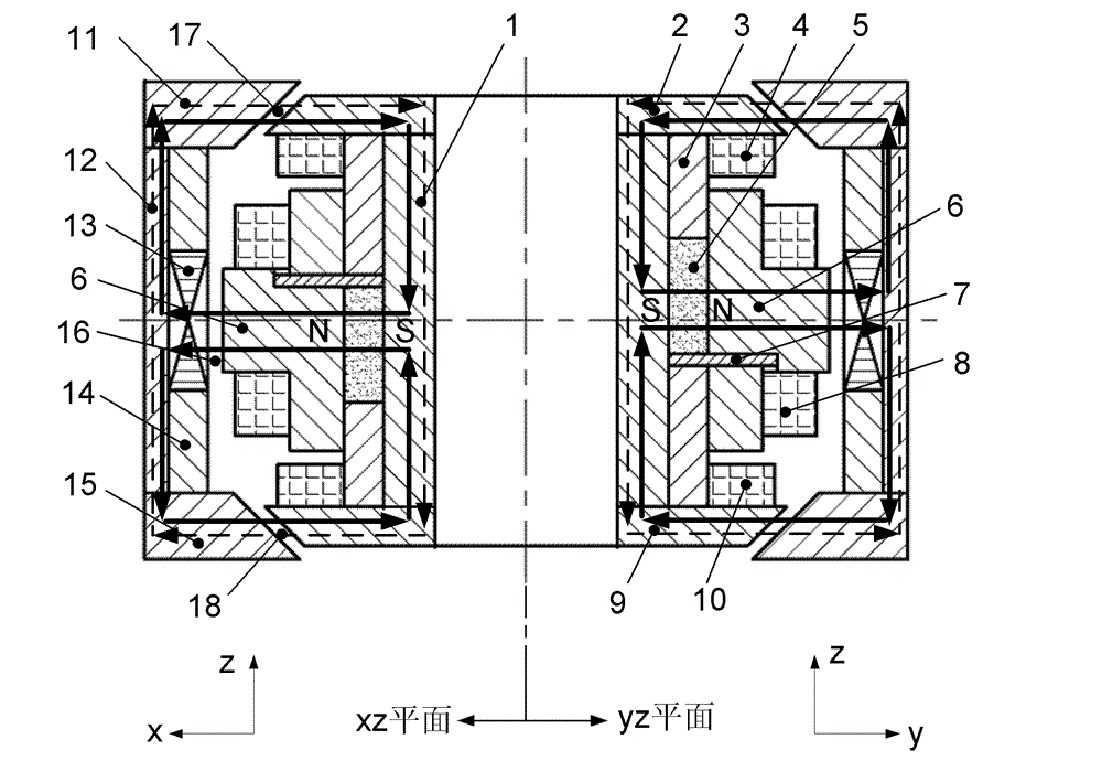
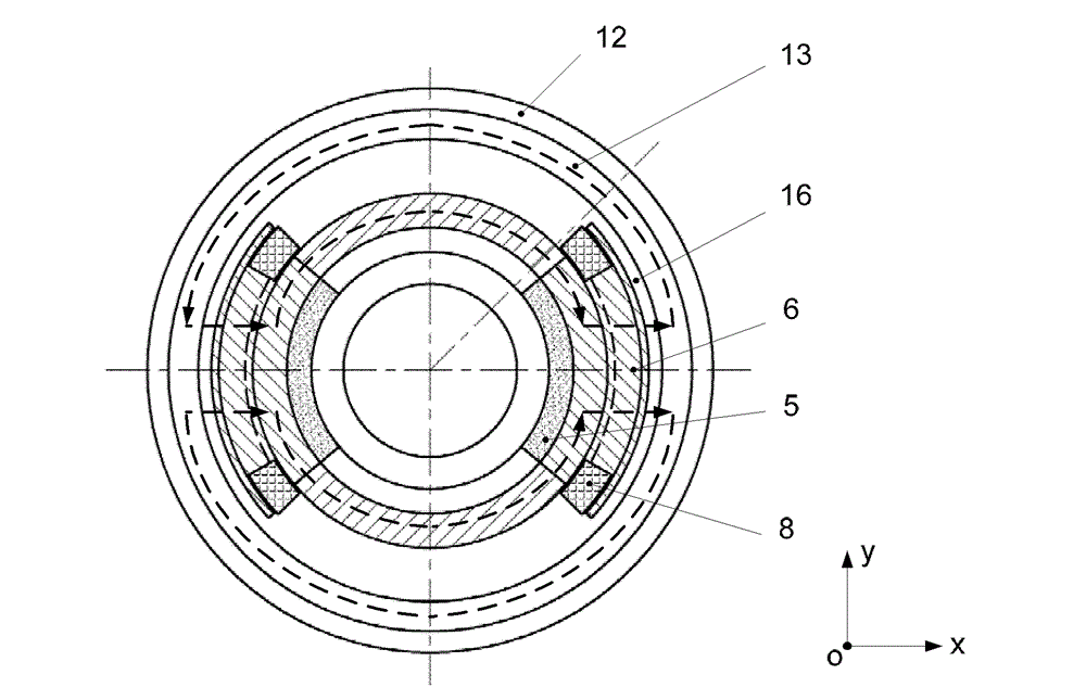
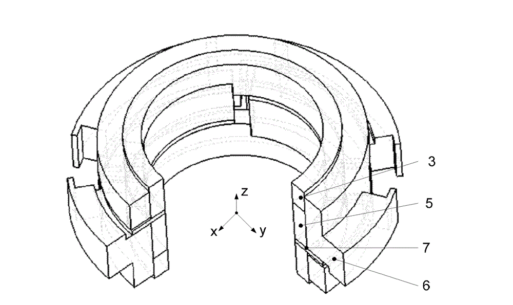
[0019] Such as figure 1 , figure 2 As shown, the present invention is generally composed of a stator part and a rotor part. The stator part includes a stator magnetic ring 1, an upper cone stator 2, a stator magnetic isolation ring 3, an axial upper coil 4, a permanent magnet 5, and a radial stator 6. , The radial stator magnetic isolation ring 7, the radial coil 8, the lower cone stator 9 and the axial lower coil 10, the rotor part includes the upper cone rotor 11, the rotor magnetic ring 12, the radial rotor core 13, the rotor magnetic isolation Ring 14, lower cone rotor 15, in which the outer side of the permanent magnet 5 is the radial stator 6. There are two radial stators 6, which are placed orthogonally along the circumferential direction. There is a radial stator magnetic isolation ring between the two radial stators. 7. Each radial stator is composed of stator teeth and stator magnetic yoke. The radial coils 8 are wound on the radial stator teeth. The upper and lower s...


PUM


Abstract

The invention discloses a radial decoupling taper magnetic bearing with three degree of freedom, comprising an upper taper stator, a lower taper stator , an upper taper rotor, a lower taper rotor, radial stators, a radial rotor iron core, a field coil, a permanent magnet, a stator magnetic conductive ring and a rotor magnetic conductive ring, wherein, the taper stators and the taper rotors are the structure of integral ring, the suction generated between the taper stator and the taper rotor passes through the rotor barycenter to control the translation in the direction z of the rotor; the two radial stators comprise stator teeth and stator magnet yokes, the two radial stators are arranged orthogonally when being installed, and a radial stator magnetic isolated ring is arranged between the two stators to let the magnetic circuit between the two radial channels be mutually decoupling; the suction generated between the radial stator and the radial rotor iron core is used to control the translation in the direction x and y of the rotor. According to the invention, the suction generated between the taper stator and the taper rotor passes through the rotor barycenter, when the rotor rotates, the length of the arm of force of negative stiffness is reduced, so that negative torsion moment is reduced; simultaneously, the two radial channels are decoupling, so that the radial bearing capacity is increased.

Description

Technical field [0001] The invention relates to a non-contact magnetic suspension bearing, in particular to a three-degree-of-freedom radially decoupled permanent magnet biased tapered magnetic bearing, which can be used as a non-contact support for rotor components in a spacecraft inertial actuator such as a magnetic suspension flywheel. Background technique [0002] With the diversified development of satellite missions, satellites have higher and higher requirements for attitude control systems. As a spacecraft attitude control actuator, maglev flywheels not only need to rely on acceleration and deceleration to output axial torque, but also need to have The function of outputting torque in radial torsion requires its support bearing to still have a large bearing capacity even when the flywheel rotor is torsion, without the negative torque effect on the flywheel rotor. In the existing magnetic levitation flywheel structure, generally a single degree of freedom axial magnetic be...

Claims


Application Information

Patent Timeline
Patent Type & Authority Patents(China)
IPC IPC(8): F16C32/04
Inventor 房建成王春娥王曦樊亚洪
Owner BEIHANG UNIV
Why Eureka
Try Eureka