
Mixed magnetic bearing with horizontal-coil uniform radial pole and low-loss outer rotor

An external rotor and coil technology, applied in the direction of bearings, shafts, bearings, shafts, etc., can solve the problems affecting the stability and accuracy of satellite attitude control, the inability to make full use of the magnetic pole circumference area, and increase the power consumption of the drive motor, etc., to achieve a compact structure , Processing and assembly are convenient, and the effect of reducing mass

Inactive Publication Date: 2011-04-06
NAT UNIV OF DEFENSE TECH
View PDF0 Cites 0 Cited by
  • Summary
  • Abstract
  • Description
  • Claims
  • Application Information

AI Technical Summary

Problems solved by technology

Therefore, for high-speed flywheel rotors, the current hybrid magnetic bearings still have obvious technical disadvantages: on the one hand, the eddy current in the rotor core will produce a significant retarding torque, which will significantly increase the driving force in aerospace applications such as magnetic levitation flywheels for attitude control. The power consumption of the motor affects the stability and accuracy of satellite attitude control; on the other hand, in order to reduce windage loss, the high-speed rotor must be enclosed in a high-vacuum shell, and the eddy current loss at this time will also bring difficulties in the design of rotor heat dissipation
In addition, the current hybrid magnetic bearing coil core and the working magnetic pole adopt an integrated structure, and there are still disadvantages such as complex structure and inability to fully utilize the circumferential area of ​​the magnetic pole.

Method used


Image

  • Mixed magnetic bearing with horizontal-coil uniform radial pole and low-loss outer rotor
  • Mixed magnetic bearing with horizontal-coil uniform radial pole and low-loss outer rotor
  • Mixed magnetic bearing with horizontal-coil uniform radial pole and low-loss outer rotor

Examples


Embodiment 1

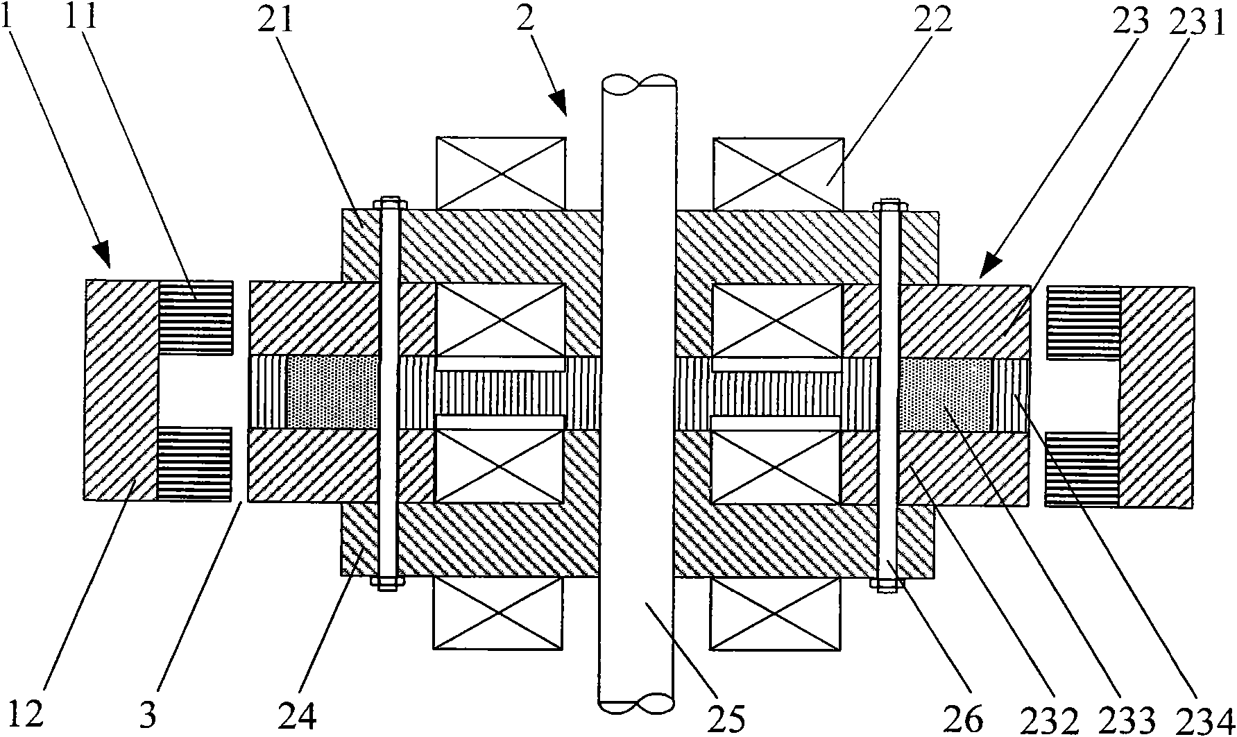
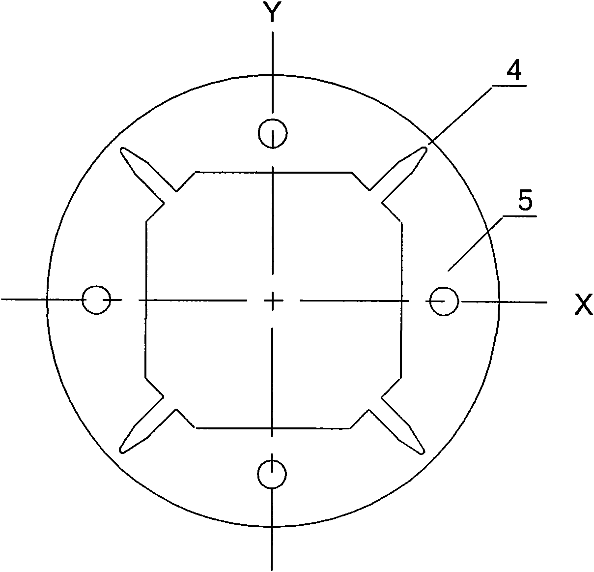
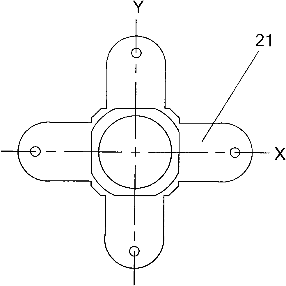
[0039] see figure 1, This embodiment of the present invention is composed of two parts, the rotor magnetically permeable ring 1 and the stator 2, such as the above-mentioned solution. The rotor magnetic ring 1 is sleeved on the outside of the stator 2 to form an outer rotor. The rotor magnetic ring 1 is composed of an outer magnetic ring 12 and a rotor core 11 , wherein the rotor core 11 is coaxially sleeved in the inner cavity of the outer magnetic ring 12 . The rotor core 11 of the rotor magnetic ring 1 is formed by punching and stacking a thin-plate soft magnetic material electrical silicon steel plate with good magnetic permeability; the stator 2 is composed of a stator plate 23, an upper magnetic cover 21, and a lower magnetic cover 24. Composed of eight electromagnetic coils 22, four connecting rods 26 and stator installation shaft 25, the four connecting rods 26 connect the upper magnetically conductive cover 21, the stator disk 23, and the lower magnetically conducti...

Embodiment 2

[0044] Such as Figure 5 As shown, two sets of figure 1 The basic structure shown can form radial four-axis active control and axial passive control magnetic bearings, that is, the present invention can be designed as a combination of multiple products of the present invention to meet different demands. For this combined magnetic bearing, a non-magnetic spacer 8 can be set between the upper and lower magnetic bearing stators, and a non-magnetic spacer 9 can be set between the upper and lower magnetic rings of the rotor. Both the partition plate 8 and the spacer ring 9 are made of non-magnetic aluminum alloy or non-magnetic stainless steel. In this embodiment, as far as the single product of the present invention is concerned, except that the magnetization directions of the permanent magnets in the upper and lower magnetic bearing stators are opposite, the others are the same as in the embodiment 1.


PUM


Abstract

The invention discloses a mixed magnetic bearing with a horizontal-coil uniform radial pole and a low-loss outer rotor, comprising a rotor magnetic conducting ring (1) and a stator (2), wherein the rotor magnetic conducting ring (1) consists of a rotor iron core (11) sleeved with the inner cavity of an external magnetic conducting ring (12); the stator (2) consists of a stator disc (23), an uppermagnetic conducting cover board (21), a lower magnetic conducting cover board (24), eight solenoid coils (22) and a stator mounting shaft (25), wherein the solenoid coils (22) are arranged horizontally and are respectively arranged at the upper side and the lower side of the stator disc (23) by taking the upper magnetic conducting cover board (21) and the lower magnetic conducting cover board (24) as coil iron cores. In the invention, the solenoid coils are arranged horizontally, take the magnetic cover boards as the coil iron cores and are separated from magnetic poles in structure, therefore, the processing and the assembly are more convenient and the magnetic poles can fully utilize circumference area to increase the bearing capability. In addition, the horizontal-coil uniform radial pole structure is more compact, thereby effectively reducing the axial height of the bearing and reducing the weight of the magnetic bearing.

Description

Technical field [0001] The invention relates to a non-contact magnetic suspension bearing, in particular to a horizontal coil radial uniform magnetic pole low-loss outer rotor hybrid magnetic bearing, which can be used as a non-contact support for rotating parts, especially for satellite attitude control magnetic suspension flywheels and energy storage flywheels No contact support. Background technique [0002] The loss of the active magnetic bearing is an important comprehensive index, which directly affects the application of the magnetic bearing. Active magnetic bearings can be divided into electromagnetic bearings and hybrid magnetic bearings with permanent magnet bias and electromagnetic control. The former must set the bias current in the electromagnetic coil to provide the working point for the magnetic bearing, so the control current is large and the power consumption is large; The hybrid magnetic bearing with magnetic bias and electromagnetic control, the permanent...

Claims


Application Information

Patent Timeline
Patent Type & Authority Patents(China)
IPC IPC(8): F16C32/04
CPCF16C32/0487F16C32/0465F16C2300/20
Inventor 刘昆张育林肖凯单小强陈小飞
Owner NAT UNIV OF DEFENSE TECH
Learn More