Method for reinforcing concrete frame joints

A technology of concrete and concrete beams, which is applied in building maintenance, construction, building construction, etc., can solve problems such as insufficient bearing capacity, increased structure self-weight, complex construction, etc., to increase rigidity and ultimate strength, increase maximum bearing capacity, and meet The effect of space requirements

Active Publication Date: 2022-04-15
JIANGSU OCEAN UNIV
View PDF6 Cites 0 Cited by
  • Summary
  • Abstract
  • Description
  • Claims
  • Application Information

AI Technical Summary

Problems solved by technology

[0002] Structural parts need to be reinforced under the following circumstances: (1) In actual engineering, the concrete often fails to reach the design strength; (2) The design standards of existing old buildings are low, the bearing capacity is insufficient, and the structure is aging, resulting in prestress hysteresis. Structural damage is relatively large; (3) function changes, such as: classrooms become libraries; (4) post-earthquake repairs
The existing reinforcement methods are: (1) Enlarging section method, the disadvantage is that it increases the self-weight of the structure itself, and may also change the stiffness distribution of the structure itself, resulting in chain reinforcement of other adjacent components; (2) Steel-clad reinforcement method , the disadvantage is high cost and complicated construction; (3) the disadvantage of adhesive anchor plate reinforcement is the limitation of the scope of application, and the reinforcement effect depends to a large extent on the bonding process and operation level; (4) the carbon fiber reinforcement method, the disadvantage The quality of the finish largely depends on the selection of carbon fiber cloth and special structural adhesive

Method used


Image

  • Method for reinforcing concrete frame joints
  • Method for reinforcing concrete frame joints

Examples


Embodiment Construction

[0026] The specific technical solutions of the present invention are further described below, so that those skilled in the art can further understand the present invention, but do not limit the rights thereof.

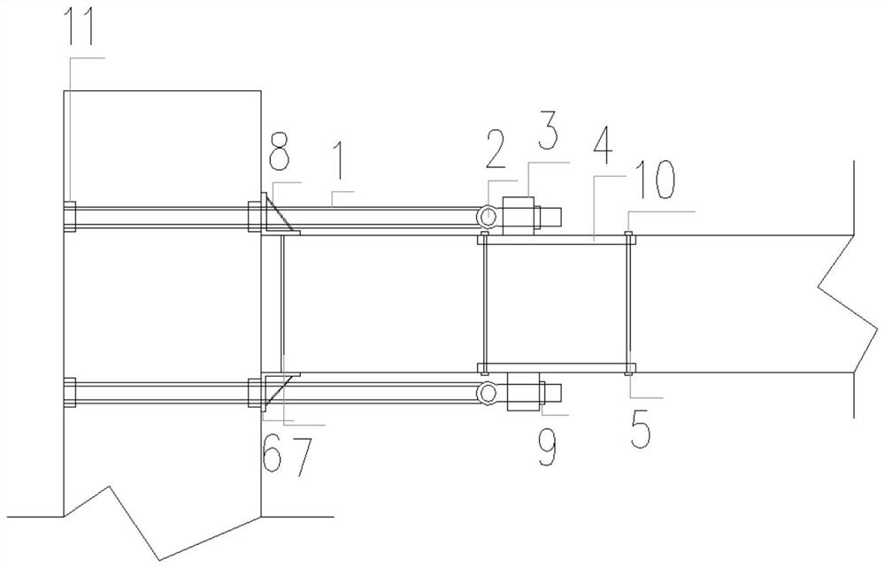
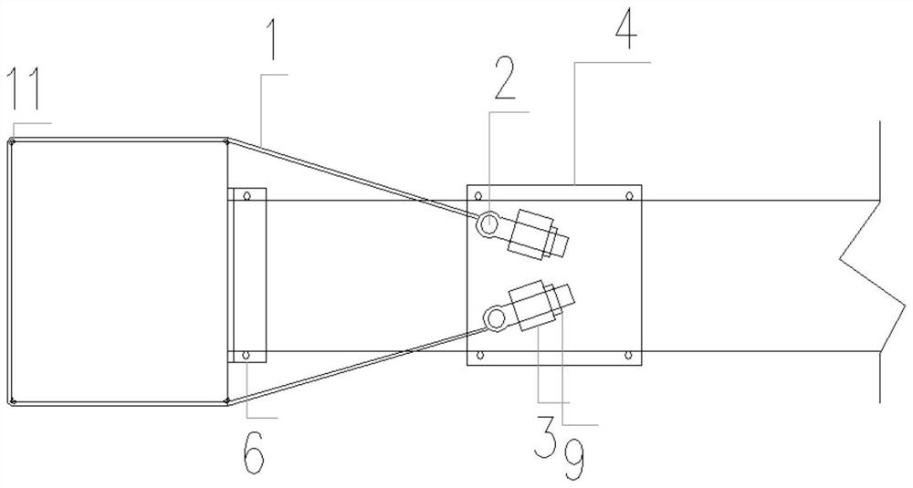
[0027] In the picture: 1. Steel wire rope, 2. Bolt with holes, 3. Cube block, 4. Special steel plate, 5. Long bolt, 6. Angle steel, 7. Long bolt, 8. Diagonal brace, 9. Nut, 10. Nut, 11. Grooved backing plate.

[0028] A method for reinforcing concrete frame joints, the steps of which are as follows:

[0029] (1) According to the area under the concrete beam, prepare a special anchoring steel plate, the area of ​​the special anchoring steel plate is larger than the area under the beam, the four corners are opened, and the special steel plate is welded with cubic steel blocks;

[0030] (2) A special rectangular steel plate is placed on the top and bottom of the near beam end, and bolt holes are reserved at the four corners of the special steel plate, and then four long ...


PUM


Abstract

A method for reinforcing concrete frame joints comprises the steps that two rectangular special anchoring steel plates on the upper surface and the lower surface of a concrete beam are embedded into upper rectangular holes and lower rectangular holes of the concrete beam respectively, holes are reserved in the four corner points of each special anchoring steel plate, and then four long bolts penetrate into reserved hole channels of the upper special steel plates and the lower special steel plates respectively; and the two special anchoring steel plates are fixedly connected to the upper and lower surfaces of the beam by screwing nuts. The steel wire rope and the heart-shaped clamp penetrate through the bolt with the hole to form a ring, the lap joint of the steel wire rope is screwed and connected through the U-shaped bolt, and then the device is inserted into the cubic blocks on the upper and lower specially-made anchoring steel plates of the beam around the column. After insertion, tensioning equipment is used for applying prestress to tighten the nut to preset applied force, so that the column is reliably connected with the beam. A groove-shaped base plate is arranged on the contact face of the steel wire rope and the column to prevent the steel wire rope from extruding concrete. And angle steel is arranged at the pressed parts of the upper and lower nodes of the beam column and is connected by long bolts. A reinforced component can have good ductility, and the maximum bearing capacity of the reinforced component is improved.

Description

technical field [0001] The invention relates to the field of civil engineering, in particular to a method for reinforcing concrete frame nodes. Background technique [0002] Structural parts need to be reinforced in the following cases: (1) In actual projects, the concrete often fails to reach the design strength; (2) The existing old buildings have low design standards, insufficient bearing capacity, and aging structures, which lead to prestress lag, Structural damage is relatively large; (3) Function changes, such as: classrooms become libraries; (4) Post-earthquake repairs. The existing reinforcement methods are: (1) The method of increasing the section, the disadvantage is that the self-weight of the structure itself is increased, and the stiffness distribution of the structure itself may also be changed, resulting in the chain reinforcement of other adjacent components; (2) The steel-clad reinforcement method , the disadvantage is that the cost is high and the construc...

Claims


Application Information

Patent Timeline
Patent Type & Authority Applications(China)
IPC IPC(8): E04G23/02E04B1/21E04B1/58
CPCE04G23/0218E04B1/215E04B1/58
Inventor 田安国秦天保李青松胡文硕
Owner JIANGSU OCEAN UNIV
Why Eureka
Try Eureka