
Flexible mechanical-hydraulic coupling device between medium and heavy-duty power plant and installation foundation

A power device and installation foundation technology, which is applied in the field of flexible mechanical hydraulic coupling devices, can solve the problems of small load capacity of liquid-resistance vibration isolators, damage to decoupling mechanisms, and limited low-frequency damping, so as to avoid high-frequency dynamic hardening , prevent structural damage, and improve the effect of low-frequency damping

Active Publication Date: 2015-12-30
SHANDONG UNIV
View PDF10 Cites 0 Cited by
  • Summary
  • Abstract
  • Description
  • Claims
  • Application Information

AI Technical Summary

Problems solved by technology

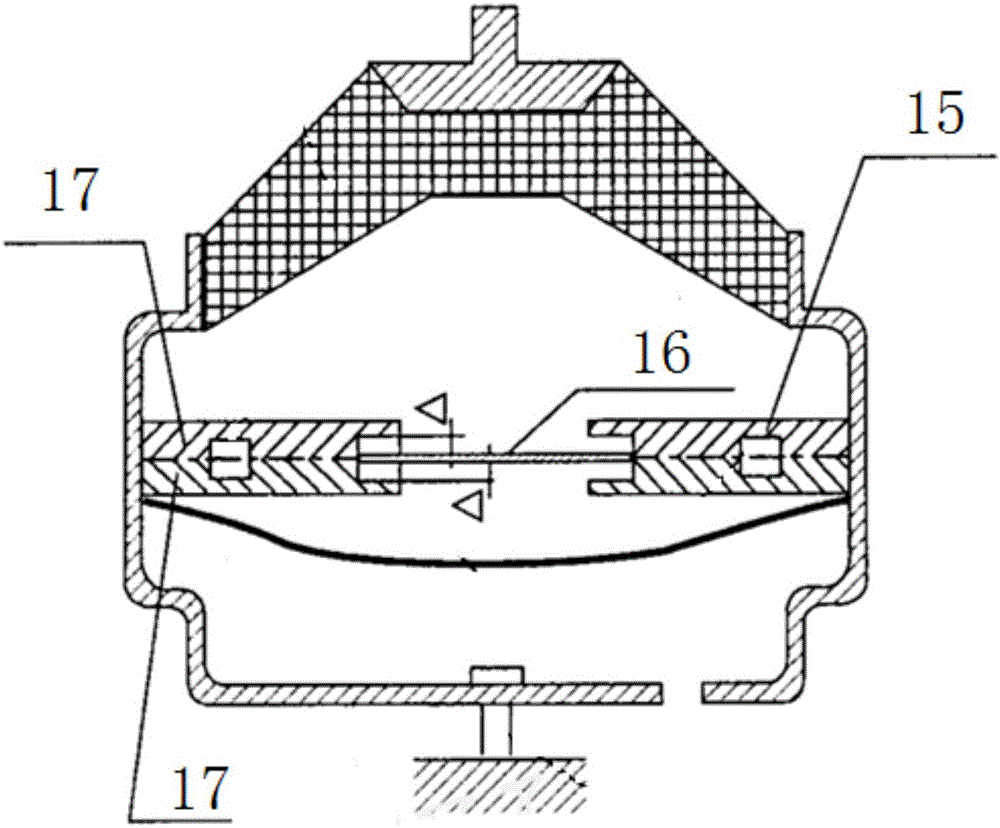
[0003] The purpose of the present invention is to overcome the above-mentioned liquid-resistance type vibration isolator's small load-bearing capacity, limited low-frequency damping, difficulty in being used as a connection, support and vibration isolation element between the medium and heavy-duty power plant and the installation foundation, and the high-frequency excitation In order to avoid the disadvantages of easy noise and even damage to the decoupling mechanism when under impact, a flexible mechanical-hydraulic coupling device between the medium and heavy-duty power plant and the installation foundation is provided. This equipment not only has a high load-bearing capacity, but also can provide The low-frequency damping and lower high-frequency dynamic stiffness are higher than those of the liquid resistance type vibration isolator, and the vibration isolation effect is better; at the same time, it can eliminate high-frequency working noise, avoid impact damage, and improve service life. It is suitable as a medium and heavy-duty power device and Joints, supports and vibration isolation elements between installation foundations

Method used


Image

  • Flexible mechanical-hydraulic coupling device between medium and heavy-duty power plant and installation foundation
  • Flexible mechanical-hydraulic coupling device between medium and heavy-duty power plant and installation foundation

Examples


Embodiment Construction

[0028] The present invention will be further described below in conjunction with the accompanying drawings and embodiments.

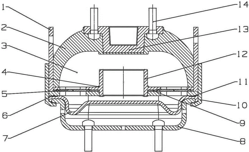
[0029] Such as figure 2 As shown, a flexible mechanical-hydraulic coupling device between a medium and heavy-duty power unit and an installation foundation includes a rubber main spring assembly, and the rubber main spring assembly includes an upper body 1 of the casing, the upper part of the upper body 1 of the casing protrudes upwards, and the outer side The lower part is fixedly connected with several connecting plates 10, and the lower ends of the connecting plates 10 protrude from the lower edge of the upper body 1 of the housing; Vulcanized together to form the rubber main spring assembly. The middle part of the upper frame 13 protrudes downwards and is located at the center of the rubber main spring 2. The head of the bolt 14 is vulcanized inside the rubber main spring 2, and the screw rod passes through the through holes on both sides of the u...


PUM


Abstract

The invention discloses a flexible mechanical hydraulic connection device between a medium and heavy power device and an installation foundation. The flexible mechanical hydraulic connection device comprises a rubber mainspring component which comprises a shell upper body, a plurality of connection plates are fixedly connected outside the shell upper body, and the lower ends of the connection plates extend out of the edge of the shell upper body; the interior of the shell upper body, a rubber mainspring, an upper framework and a bolt are vulcanized together, the upper framework is positioned in the center of the rubber mainspring, and the bolt is connected with the upper framework and the rubber mainspring; a partition and a liquid column passage component are arranged on the lower portions of the rubber mainspring and the upper framework, a cavity among the rubber mainspring, the upper framework, the partition and the liquid column passage component is an upper liquid chamber, a shell lower body component is arranged below the partition and the liquid column passage component, a space among the partition, the liquid column passage component and the shell lower body component is a lower liquid chamber, and the upper liquid chamber and the lower liquid chamber are communicated through the partition and a liquid column passage of the liquid column passage component; the lower ends of the connection plates are in clamped connection with the upper edge of a shell lower body of the shell lower body component through bending portions.

Description

technical field [0001] The invention relates to a flexible mechanical-hydraulic connection device between a power device and an installation foundation, which is mainly used for connection, support and vibration isolation between a medium and heavy-duty power device and the installation foundation. Background technique [0002] At present, in order to effectively support and isolate the power plant, the power plant and the installation base are usually connected by flexible elements (such as pure rubber vibration isolators and liquid resistance type vibration isolators, etc.). The size and structure of the pure rubber vibration isolator are relatively flexible, and can be designed according to the load-bearing requirements of different power devices. However, this type of vibration isolator has small damping in the low-frequency excitation range of 0-50Hz, and it is difficult to adjust the low-frequency and large-amplitude vibration of the power device. Vibration is effectiv...

Claims


Application Information

Patent Timeline
Patent Type & Authority Patents(China)
IPC IPC(8): F16F13/08
Inventor 王亚楠吕振华
Owner SHANDONG UNIV
Learn More