Control system for lampblack concentration detecting device

A detection device and oil fume concentration technology, which is applied in the control system field of the oil fume concentration detection device, can solve the problems of missing data, waste of adsorption medium, and the oil fume purifier has been turned on, and achieve the effect of accurate data and reduced detection cost

A detection device and oil fume concentration technology, which is applied in the control system field of the oil fume concentration detection device, can solve the problems of missing data, waste of adsorption medium, and the oil fume purifier has been turned on, and achieve the effect of accurate data and reduced detection cost

CN102322657AActive Publication Date: 2012-01-18GUANGZHOU ZHENGHONG TECH DEV

Image

  • Control system for lampblack concentration detecting device
  • Control system for lampblack concentration detecting device
  • Control system for lampblack concentration detecting device

Examples


Embodiment 1

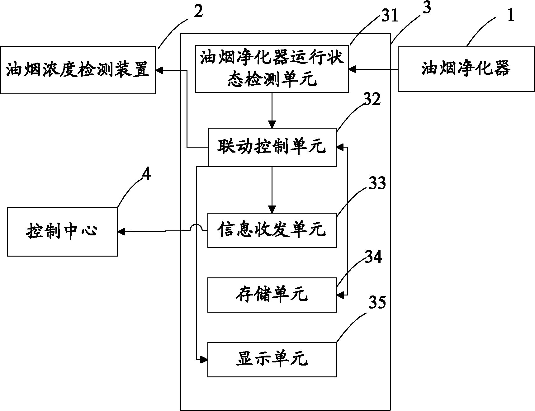
[0034] see figure 1 , the control system of the soot concentration detection device in this embodiment includes:

[0035] Linkage monitoring device 3, including:

[0036] The oil fume purifier operating state detection unit 31 is used to receive the operating state signal of the oil fume purifier 1;

[0037] The linkage control unit 32 starts the oil fume concentration detection device 2 when the operation state signal indicates that the oil fume purifier 1 is started; and turns off the oil fume concentration detection device 2 when the operation state signal indicates that the oil fume purifier is closed;

[0038] An information transceiving unit 33, configured to receive the detection data of the oil fume concentration detection device 2 and transmit it to the external control center 4;

[0039] a storage unit 34, configured to store the detection data of the oil fume concentration detection device;

[0040] The display unit 35 displays the detection data of the oil fume ...

Embodiment 2

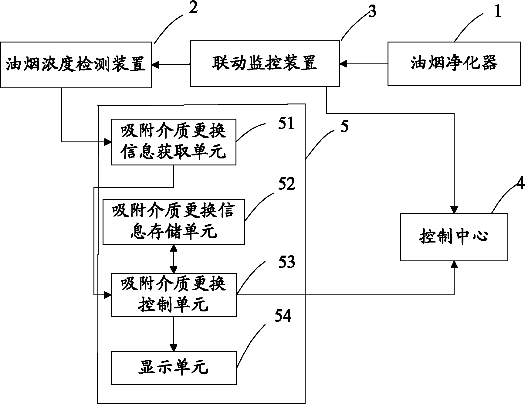
[0048] see figure 2 The difference between this embodiment and Embodiment 1 is that, in this embodiment, the control system of the oil fume concentration detection device includes, in addition to the linkage monitoring device, an adsorption medium management device 5 for monitoring the use status of the adsorption medium.

[0049] The adsorption medium management device 5 includes:

[0050] The adsorption medium replacement information acquisition unit 51 is used to obtain the current adsorption medium replacement information; that is, the information is obtained when the adsorption medium is replaced;

[0051] The adsorption medium replacement information storage unit 52 is used to store the historical information of the replacement of the adsorption medium; that is, to store the replacement information of the adsorption medium each time;

[0052]The adsorption medium replacement control unit 53 is used to send a signal representing the exhaustion of the adsorption medium t...


PUM


Abstract

The invention discloses a control system for a lampblack concentration detecting device. The control system comprises a link monitoring device, a lampblack purifier operation state detection unit and a link control unit, wherein the link monitoring device is used for controlling a lampblack detection device to operate; the lampblack purifier operation state detection unit is used for receiving anoperation state signal of the lampblack purifier; and the link control unit is used for starting the lampblack concentration detecting device when the operation state signal represents the start of the lampblack purifier and closing the lampblack concentration detecting device when the operation state signal represents the closing of the lampblack purifier. According to the control system disclosed by the invention, the lampblack concentration detecting device can synchronously work together with the lampblack purifier; the time blank is avoided; data detected by the lampblack concentration detecting device are more accurate and complete; the supervision work of environmental protection departments can be effectively realized; meanwhile, the phenomenon that energy sources are wasted because the lampblack purifier does not operate and the lampblack concentration detecting device operates is avoided; and the detection cost is reduced.

Description

technical field [0001] The invention relates to the field of oil fume purifiers, in particular to a control system for an oil fume concentration detection device. Background technique [0002] Currently, the catering industry is booming. Restaurants and restaurants will inevitably produce a lot of oil fumes during the cooking process. This oil fume has a great impact on the production and life of enterprises and residents around the catering enterprise. For this reason, the environmental protection department requires catering companies to install and use lampblack purifiers to reduce the impact of lampblack on people and the environment. [0003] At present, the most used and effective oil fume purifiers are mainly electrostatic oil fume purifiers. Its working principle is: the polarized area of ​​the purifier polarizes or charges the oil particles in the oil fume, making them charged. , and then let the charged oil particles pass through the plate with high voltage, and...

Claims


Application Information

Patent Timeline
18 Jan 2012
Publication
CN102322657A
IPC
F24C15/20
Inventors
ι»„εš; ζŽι‡‘εŽ