Fixture for tensile bonding strength test of solid propellant and coating

A technology of tensile bonding strength and solid propellant, which is applied in the field of explosive performance testing, can solve the problems of difficult coaxial alignment, large error in measurement results, and small degree of freedom of fixtures, and achieves easy coaxial alignment, Guaranteed accuracy and large activity space

Inactive Publication Date: 2012-01-18
XIAN MODERN CHEM RES INST
View PDF3 Cites 30 Cited by
  • Summary
  • Abstract
  • Description
  • Claims
  • Application Information

AI Technical Summary

Problems solved by technology

The above-mentioned test fixture and test method have the following disadvantages: (1) the fixture structure is complicated, the volume is large, and the quality is large, and it is difficult to replace and maintain the fixture, especially the large-volume fixture is not conducive to operation in the high and low temperature test chamber; (2) When carrying out the tensile test, it is easy to pinch and damage the surface of the sample when the spring automatically locks the non-slip toothed flat plate or V-shaped groove fixture automatically, thus causing the sample to break from the limit position, resulting in test failure; (3) ) For a columnar propellant sample with high strength, it is easy for the sample to “pull off” from the fixture. At the same time, due to the small degree of freedom of the fixture, it is not easy to be centered on the same axis, and it is easy to force it when clamping the columnar sample. Damaged, resulting in large errors in measurement results

Method used


Image

  • Fixture for tensile bonding strength test of solid propellant and coating
  • Fixture for tensile bonding strength test of solid propellant and coating
  • Fixture for tensile bonding strength test of solid propellant and coating

Examples


Embodiment Construction

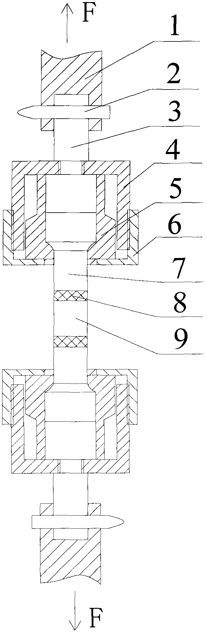
[0012] The present invention will be further described in detail below in conjunction with the accompanying drawings and preferred embodiments.

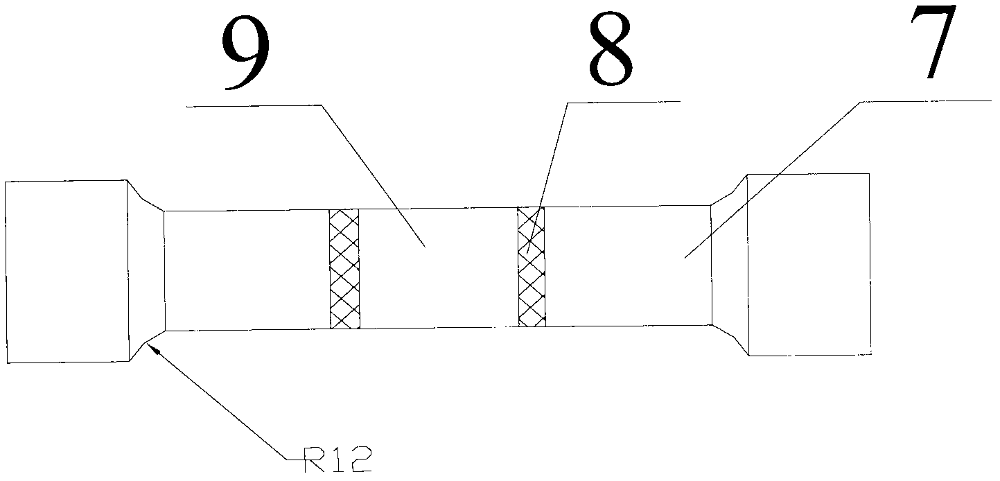
[0013] as figure 1 As shown, the test fixtures for the bond strength between the solid propellant and the cladding layer of the present invention are two sets of fixtures that are used symmetrically and have the same structure. Each set of fixtures includes a connecting rod 3, a fixed seat 4, a compression nut 6, two semicircular Wrist set 5, sample joint 7. All components except the sample joint 7 are made of stainless steel. The connecting rod 3 is cylindrical, one end has a radial through hole connected with the pull rod 1 of the tensile testing machine, and a section of threaded rod protrudes from the center of the other end face. The cylinder size of the connecting rod 3 is determined according to the diameter of the installation hole of the tensile testing machine pull rod 1. For the tensile testing machine pulling rod 1 of d...


PUM

PropertyMeasurementUnit
diameteraaaaaaaaaa
thicknessaaaaaaaaaa

Abstract

The invention discloses a fixture for tensile bonding strength test of solid propellant and coating, belonging to the field of test of explosive performance. The fixture comprises two sets of fixtures which are used symmetrically and have the same structure. Before test, the two ends of a propellant test sample are bonded on the small-diameter end faces of two coating test sample joints through a test adhesive respectively; two connecting rods are correspondingly and fixedly connected to pull rods on both sides of a tensile testing machine; two fixing seats are in threaded connection with the connecting rods; and the large-diameter ends of the two test sample joints and a limiting groove are fixed in corresponding fixing seats through two compression nuts in cooperation with two pairs of semicircular wristlets. According to the fixture, the problems of easy damage to the surface of the test sample and easy slippage and looseness of the test sample during low-temperature test, existing in the conventional tensile test fixture, are solved. Meanwhile, the test fixture has the advantages of simple structure, light weight, small size, convenience for clamping, high centering accuracy and the like.

Description

technical field [0001] The invention belongs to the field of propellant performance testing, and mainly relates to a fixture for testing the bonding strength of a solid propellant and a cladding layer, in particular to a fixture suitable for testing the tensile bond strength of a solid propellant and a cladding layer. Background technique [0002] The cladding layer plays a vital role in the orderly and controlled combustion of solid propellants. The quality of the bonding performance between the cladding layer and the surface of the solid propellant grain will directly affect the launch safety of the rocket motor. Bonding strength is an important index to evaluate the bonding performance of solid propellant and cladding layer. At present, the methods for measuring the bonding strength of solid propellant and cladding layer include wheel peeling method and tensile method. In the current tensile test, flat plate or V-groove clamps with anti-slip teeth are generally used in Ch...

Claims


Application Information

Patent Timeline
Patent Type & Authority Applications(China)
IPC IPC(8): G01N3/04
Inventor 张林军陈竚邵颖惠任黎曹继平张皋李军强马亚南曹磊
Owner XIAN MODERN CHEM RES INST
Why Eureka
Try Eureka