
Control design method of regional clock cassette mechanism

A design method and regional clock technology, applied to clocks, master clocks, electromechanical clocks, etc., can solve the problems of increasing the load of the sub-wheel shaft, complex deceleration transmission mechanism, poor visual effect, etc., to reduce the load and save processing Process and material costs, the effect of improving economic efficiency

Inactive Publication Date: 2013-04-17
烟台钟表研究所有限公司 +1
View PDF6 Cites 4 Cited by
  • Summary
  • Abstract
  • Description
  • Claims
  • Application Information

AI Technical Summary

Problems solved by technology

As the terminal sub-clock movement of the intelligent regional clock, this clock movement has played a positive role in advancing the analog clock to the regional clock, but there are also obvious technical defects. The disc causes the photoelectric detection disc to be repeatedly set on the sub-wheel shaft and the sub-wheel piece, which not only increases the carrying load of the sub-wheel shaft but also wastes materials and increases costs; the second is that there is no second hand transmission device, and the existing second hand transmission publicly used at home and abroad is The second wheel shaft is meshed with the stepping motor through a two-stage gear reduction transmission mechanism. Not only is the reduction transmission mechanism complicated, but also the driving of the stepping motor drives the second hand to run with jumping needles, and its visual effect is not good; the third is the existing use area The clocks are directly powered by 220V main power supply. Once the main power supply is disconnected, the terminal clocks will all stop, which is especially easy to cause an illusion to passengers and cause delays in time; Issues urgently needed to be solved by technicians in the technical field

Method used


Image

  • Control design method of regional clock cassette mechanism
  • Control design method of regional clock cassette mechanism

Examples


Embodiment 1

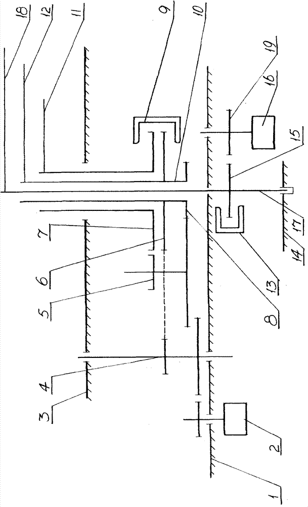
[0019] The regional clock movement of embodiment 1 of the present invention (referring to figure 1 ), it is a clock movement designed and improved based on the movement used in the three-pin sub-clock of the intelligent sub-master clock system that is suitable for public places such as ships, hotels, stations, and docks and is used for unified control in this area. The clock movement in this area mainly includes: the front splint 3 and the middle splint 1 of the movement form the supporting frame of the gear train transmission shaft of the clock movement, the stepping motor 2 is fixedly installed on the middle splint 1, and the output of the stepping motor 2 The gear at the end is meshed with the large gear of the gear reduction transmission assembly 4, and the pinion of the gear reduction transmission assembly 4 is directly meshed with the minute wheel 6 fixedly installed on the minute wheel shaft 10. This structure is formed by the stepping motor 2 to The two-stage 12:1 gear...

Embodiment 2

[0021] The regional clock movement of embodiment 2 of the present invention (referring to figure 1), it is a clock movement designed and improved based on the movement used in the three-pin sub-clock of the intelligent sub-master clock system that is suitable for public places such as airports, subways, and high-speed rails and used within a certain area. The technical requirements of the movement are: accurate travel time, hour and minute hand calibration, fast dialing does not affect the operation of the second hand, the second hand operates in a continuous movement mode, and the second hand and the minute hand run in full minutes and zero seconds. For this reason, except that the technical solution set in this embodiment 2 is completely the same as the technical solution described in embodiment 1 of the present invention, it also has the following differences: one is to further meet the technical requirements of this embodiment, the described The synchronous geared motor 16...


PUM


Abstract

The invention discloses a control design method of a regional clock cassette mechanism, which belongs to the technical field of timing instruments. The regional clock cassette mechanism comprises a cassette mechanism splint, a stepper motor, a clock hand component and a gear reducing transmission mechanism; the control design method of the regional clock cassette mechanism has the characteristicsthat: the regional clock cassette mechanism comprises a synchronous reducing motor, a gear on the output end of the synchronous reducing motor is directly meshed and connected with a second wheel which is directly arranged on a second wheel shaft, and a hole is arranged on the second wheel and a photoelectric switch is respectively arranged on both ends of the hole. The control design method comprises the steps of power supply to the clock cassette mechanism, the driving to a time base, an hour hand, a minute hand and a second hand, and the setting and the control of alarm information feedback items. Compared with the prior art, the control design method of the regional clock cassette mechanism has the significant and substantial characteristics and significant progress that: the second hand continuously works, a clock can still work for three hours after a 220V main power supply is disconnected to wait for the connection of the main power supply; but if the power from the main power supply is still not obtained, the hour hand and the minute hand are automatically reset to a 12 o'clock position, so that the alarm information that 'the clock fails to work, please pay attention and do not delay the travel time' and the like is sent to a traveler.

Description

[0001] This application is a divisional application for an invention patent filed on April 10, 2010 by the applicants: Yantai Watch Institute Co., Ltd. and Yantai Polaris High-Based Time Synchronization Technology Co., Ltd. The original application number: 201010145962.8, the name of the invention The invention is: a regional clock movement and a control design method. technical field [0002] The invention relates to the technical field of timing instruments, in particular to a regional clock movement suitable for regional installation, remote control and automatic calibration and a control design method. Background technique [0003] With the rapid development of urban construction, especially the continuous completion of new modern transportation hubs such as stations, ports, airports, and subways, the analog clock not only provides decorative embellishments for public places, but more importantly, it Provide time display and time telling services to mobile people, and co...

Claims


Application Information

Patent Timeline
Patent Type & Authority Patents(China)
IPC IPC(8): G04C3/14G04C10/00G04C13/00
Inventor 马兴邦莫里斯·高基季文萍孙建伟曲绍坤王倩曲琳
Owner 烟台钟表研究所有限公司
Learn More