Insulated gate bipolar transistor (IGBT) driving circuit

A driving circuit and circuit technology, applied in the direction of electrical components, output power conversion devices, etc., can solve problems such as inconvenience, and achieve the effects of reducing discharge and turn-off speed, reducing voltage variation, and suppressing excessive collector voltage.

Active Publication Date: 2012-01-18
EAST GRP CO LTD
View PDF5 Cites 26 Cited by
  • Summary
  • Abstract
  • Description
  • Claims
  • Application Information

AI Technical Summary

Problems solved by technology

[0008] But in this kind of circuit, Rg2 can't be too small, otherwise the dv / dt will be very high when the IGBT is turned off, and it must rely on various external absorption circuits to Complete overvoltage suppression, not convenient enough

Method used


Image

  • Insulated gate bipolar transistor (IGBT) driving circuit
  • Insulated gate bipolar transistor (IGBT) driving circuit
  • Insulated gate bipolar transistor (IGBT) driving circuit

Examples


Embodiment Construction

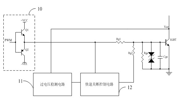
[0017] see figure 2 , figure 2 It is a structural schematic diagram of the first embodiment of the IGBT driving circuit of the present invention.

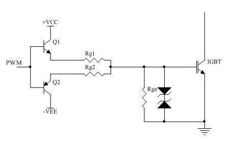
[0018] The IGBT driving circuit of the present invention includes: a turn-on resistor Rg1, a turn-off resistor Rg2 and a switch input circuit 10, the switch input circuit 10 may be a wire or an interface for inputting a switch voltage signal of a switch IGBT gate.

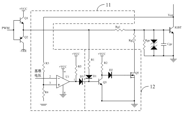
[0019] The switch input circuit 10 is connected to the gate of the IGBT through the turn-on resistor Rg1; one end of the turn-off resistor Rg2 is connected to the gate of the IGBT. The IGBT drive circuit of the present invention also includes an overvoltage detection circuit 11 and a fast shutdown control circuit 12 connected to each other; the overvoltage detection circuit 11 is connected to the collector of the IGBT to detect the collector voltage of the IGBT; The quick turn-off control circuit 12 is connected to the other end of the turn-off resistor Rg2, and con...


PUM


Abstract

The invention provides an insulated gate bipolar transistor (IGBT) driving circuit, which comprises a switching-on resistor with a relatively higher resistance value, a switching-off resistor with a relatively lower resistance value and a switching input circuit, wherein the switching input circuit is connected to the gate of an IGBT by the switching-on resistor; and one end of the switching-off resistor is connected to the gate of the IGBT. The IGBT driving circuit further comprises an over-voltage detection circuit and a rapid switching-off control circuit. The rapid switching-off control circuit controls the other end of the switching-off resistor to be switched off when the switching input circuits inputs a switching-on level, controls the other end of the switching-off circuit to be grounded when the switching input circuit inputs a switching-off level, and controls the other end of the switching-off resistor to be switched off when the voltage, detected by the over-voltage detection circuit, of the collector of the IGBT is higher than a preset value. The IGBT driving circuit provided by the invention can rapidly realize the rapid switching-off of the IGBT and simultaneously suppress the excessive voltage variations of the IGBT.

Description

technical field [0001] The invention relates to the technical field of power supply control, in particular to an IGBT driving circuit. Background technique [0002] As we all know, IGBT (Insulated Gate Bipolar Transistor, insulated gate bipolar transistor) will have conduction loss and switching loss during operation. These power losses usually appear as heat, and a heat sink must be used to transfer the heat from power devices to External environment, if the heat sink is not properly designed, these power devices may be damaged due to overheating, so in many applications, the maximum output power of the IGBT is often limited by the thermal design. [0003] Usually, the total average loss of IGBT P T =Psat+Psw, where Psat is the on-state loss of the IGBT, and Psw is the switching loss of the IGBT. [0004] Therefore, the way to reduce the IGBT loss is to reduce the IGBT on-state loss or switching loss, and the on-state loss is generally determined by the saturation voltag...

Claims


Application Information

Patent Timeline
Patent Type & Authority Applications(China)
IPC IPC(8): H02M1/08
Inventor 戴宝锋
Owner EAST GRP CO LTD
Why Eureka
Try Eureka