Ultrasonic diagnosis instrument with RFID (radio frequency identification) function

An ultrasonic diagnosis, RFID tag technology, applied in the direction of sonic diagnosis, ultrasonic/sonic/infrasonic diagnosis, infrasound diagnosis, etc., can solve the problems of cumbersome manual input, low work efficiency, easy to make mistakes, etc.

Active Publication Date: 2012-01-25
SHANTOU INST OF UITRASONIC INSTR CO LTD
View PDF4 Cites 6 Cited by
  • Summary
  • Abstract
  • Description
  • Claims
  • Application Information

AI Technical Summary

Problems solved by technology

[0004] The current ultrasonic diagnostic instruments generally only have the function of collecting the diagnostic information of the measured object. For the identification information such as the type, name or other basic characteristics of the measured object, it is necessary to use the keyboard for manual entry, which is cumbersome. Moreover, the utilization rate of ultrasonic diagnostic instruments is reduced, resulting in low overall work efficiency, and manual entry at the detection site is also prone to errors

Method used


Image

  • Ultrasonic diagnosis instrument with RFID (radio frequency identification) function
  • Ultrasonic diagnosis instrument with RFID (radio frequency identification) function
  • Ultrasonic diagnosis instrument with RFID (radio frequency identification) function

Examples


Embodiment 1

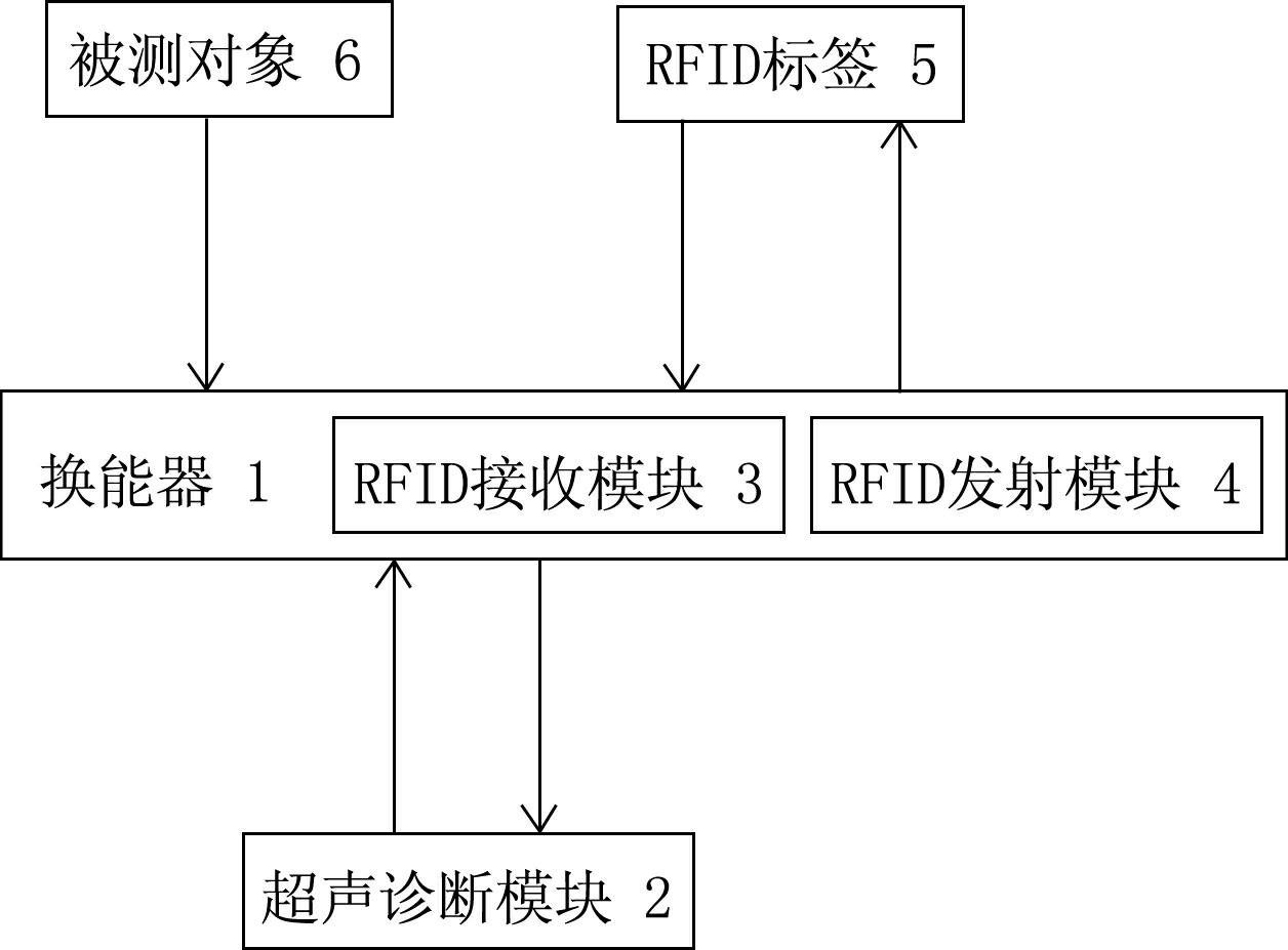
[0019] Such as figure 1 As shown, this ultrasonic diagnostic instrument with RFID function includes a transducer 1, an ultrasonic diagnostic module 2, an RFID receiving module 3 and an RFID transmitting module 4; the transducer 1 receives a control signal from the ultrasonic diagnostic module 2, and The collected current diagnostic information is converted into an electrical signal and uploaded to the ultrasonic diagnostic module 2; the RFID receiving module 3 receives the radio frequency signal from the RFID tag 5, demodulates and decodes it and uploads it to the ultrasonic diagnostic module 2; the RFID transmitting module 4 receives the radio frequency signal from the RFID tag 5; The identification information and current diagnosis information of the ultrasonic diagnosis module 2 , modulate and code the identification information and current diagnosis information, and then transmit corresponding radio frequency signals to write the identification information and current diagn...

Embodiment 2

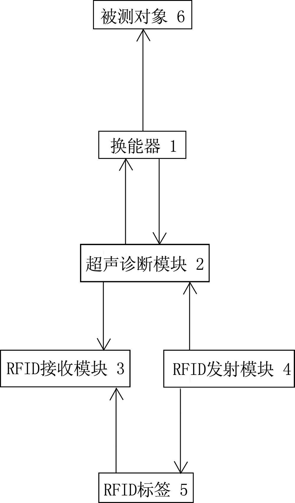
[0024] Such as figure 2 As shown, in the case that other parts are all the same as Embodiment 1, the difference is that the RFID receiving module 3 and the RFID transmitting module 4 are all arranged in the transducer 1, that is, the RFID receiving module 3 and the RFID transmitting module 4 are connected to the transducer 1. The transducers 1 are in the same housing.


PUM


Abstract

The invention relates to an ultrasonic diagnosis instrument with a RFID (radio frequency identification) function. The ultrasonic diagnosis instrument comprises a transducer and an ultrasonic diagnosis module, wherein the transducer is used for receiving control signals from the ultrasonic diagnosis module, and uploading the collected diagnosis information to the ultrasonic diagnosis module. The ultrasonic diagnosis instrument is characterized by also comprising a RFID receiving module, wherein the RFID receiving module is used for receiving radio frequency signals from a RFID label, demodulating and decoding the signals, and then uploading the signals to the ultrasonic diagnosis module. The ultrasonic diagnosis instrument has the characteristics that when writing-in is carried out on the RFID label in advance, enough time is provided for repeated proofreading, thus the identification information can be accurately written-in, and the reading-out accuracy from the RFID label is ensured; and when the object to be detected is detected (or diagnosed), the identification information of the detected object is read while diagnosing, long-time complicated entering operation is not required, the detection process is more fluent, the working efficiency of the ultrasonic diagnosis instrument with the RFID function is greatly improved, and the whole working efficiency is further improved.

Description

technical field [0001] The invention relates to an ultrasonic diagnostic equipment, in particular to an ultrasonic diagnostic instrument with RFID function. Background technique [0002] Radio Frequency Identification (RFID), or radio frequency identification technology, is a non-contact automatic identification technology that emerged in the 1990s. A set of RFID identification system usually includes RFID tags, RFID receivers and RFID transmitters; for RFID tags, through RFID transmitters, radio waves of a certain frequency are used as carriers (that is, radio frequency signals of a certain frequency are emitted), and the representative The serial number of the measured object (including human body, animal or other objects) is modulated, coded, and written into the RFID tag; while the RFID receiver receives the radio frequency signal sent by the RFID tag, decodes it, and restores the corresponding Represents the serial number of the measured object, that is, reads the RFID...

Claims


Application Information

Patent Timeline
Patent Type & Authority Applications(China)
IPC IPC(8): A61B8/00
Inventor 吴小鹏陈亚沛李德来
Owner SHANTOU INST OF UITRASONIC INSTR CO LTD
Why Eureka
Try Eureka