Three-cavity dosing device for sewage treatment and dosing method thereof

A sewage treatment and dosing device technology, applied in water/sewage treatment, water/sludge/sewage treatment, flocculation/sedimentation water/sewage treatment, etc. solution effects and other issues, to achieve the effect of exerting the efficacy of medicine and reducing the waste of medicine solution

Inactive Publication Date: 2012-01-25
BAOSTEEL DEV CO LTD
View PDF5 Cites 8 Cited by
  • Summary
  • Abstract
  • Description
  • Claims
  • Application Information

AI Technical Summary

Problems solved by technology

However, when this kind of device is in the cycle of dosing and water supply in the cyclic dosing stage, the liquid medicine flows from the curing tank to the storage tank through the overflow weir. Since the medicine liquid flows in continuously while maturing, it is easy to cause uneven aging of the medicine liquid and cause As a result, the immature medicament enters the storage tank, which cannot maximize the efficacy of the medicine and reduces the effect of the medicine solution. In order to achieve the predetermined treatment effect, it is necessary to increase the dosage of the medicine. This situation is more obvious for water treatment sites with discontinuous dosing; Secondly, this kind of dosing device is only equipped with an emptying device. After the dry powder dosing system and the water supply system stop working in the final stage, the remaining liquid medicine in each tank (especially the dissolution tank and aging tank) is not used. For discontinuous dosing Water treatment places, such as small and medium-sized water treatment plants that only treat 8 hours a day, will waste a lot of residual liquid medicine

Method used


Image

  • Three-cavity dosing device for sewage treatment and dosing method thereof

Examples


Embodiment Construction

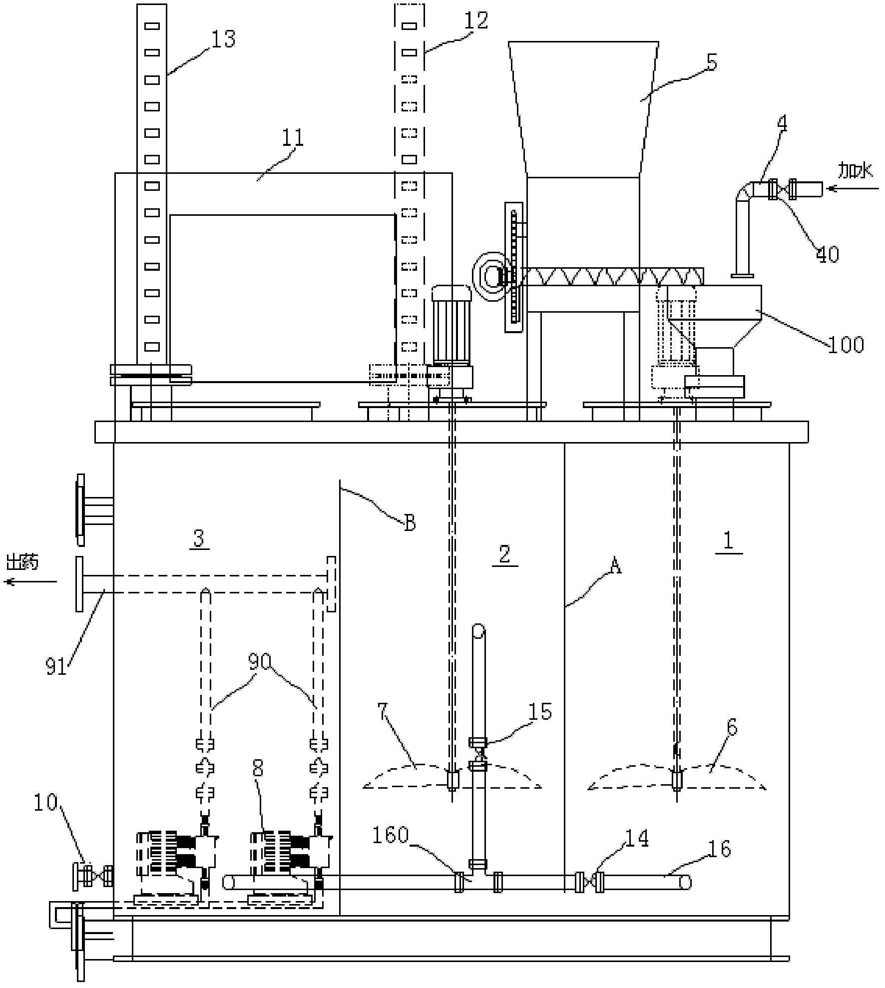
[0034] Such as figure 1 As shown, a three-chamber dosing device for sewage treatment includes a dissolving box and a control box 11 arranged above the dissolving box, and the inside of the dissolving box is divided into three parts by two weir plates A and B. There are three cavities, which are dissolving cavity 1, curing cavity 2 and storage cavity 3 respectively, and the two adjacent cavities communicate with each other.

[0035] There is a feeding hopper 100 on the dissolving chamber 1, a water supply system 4 and a dry powder dosing system 5 are arranged above the feeding hopper, and a mixer 6 controlled by a motor is arranged in the dissolving chamber;

[0036] A stirrer 7 controlled by a motor and a liquid level gauge 12 in the curing chamber are arranged in the curing chamber 2,

[0037] A storage chamber liquid level gauge 13 is provided in the storage chamber 3, and a metering pump 8 is provided at the bottom of the storage chamber. There is a vent valve 10;

[003...


PUM


Abstract

The invention relates to a three-cavity dosing device for sewage treatment. The device comprises a chemical dissolving case and a control case, wherein the inside of the chemical dissolving case is divided into a dissolving cavity, a curing cavity and a storing cavity, a feed hopper is arranged on the dissolving cavity, a water supply system and a dry powder dosing system are arranged above the feed hopper, and a motor-controlled stirrer is arranged in the dissolving cavity; a stirrer and a curing cavity liquid level meter are arranged in the storage cavity; a metering pump is arranged at thebottom of the storage cavity, and is communicated with a chemical discharge tube which passes through a pipeline and penetrates out of the storage cavity; an air release valve is arranged at the bottom of the storage cavity; the dissolving cavity and the curing cavity are communicated at the bottom of the chemical dissolving case, while the curing cavity and the storage cavity are communicated onthe top of the chemical dissolving case; a horizontal pipeline communicated with the storage cavity from the dissolving cavity is arranged at the bottom of the chemical dissolving case, and an electromagnetic valve at one end, positioned in the dissolving cavity, of the horizontal pipeline; the middle part of the horizontal pipeline is connected with a vertical pipeline in the curing cavity through a tee-joint; and an electromagnetic valve is arranged on the vertical pipeline.

Description

technical field [0001] The invention relates to a dosing device for sewage treatment, in particular to a three-chamber dosing device for sewage treatment. The invention also relates to a method for adding medicine to the medicine adding device. Background technique [0002] With the country's higher and higher requirements for energy saving and emission reduction, the large demand for water treatment and dosing equipment is an inevitable trend. The dosing devices in the prior art include double-chamber and three-chamber types. The liquid medicine is transferred between the two cavities of the double-chamber dosing device through a liquid medicine lifting pump, but this kind of device consumes more electricity; the application number is 200920223644.1 The Chinese utility model patent discloses an "automatic dosing device for sewage treatment". The device is equipped with a pre-soaking device between the powder doser and the dissolving box, which can pre-soak the dry floccula...

Claims


Application Information

Patent Timeline
Patent Type & Authority Applications(China)
IPC IPC(8): B01F15/02B01F1/00B01F7/16C02F1/00C02F1/52B01F15/04
Inventor 陆泉宝肖海彦
Owner BAOSTEEL DEV CO LTD
Why Eureka
Try Eureka