
Main driving mechanism of intermediate-speed needling machine

A main drive, acupuncture machine technology, applied in acupuncture machines, transmission devices, mechanical equipment and other directions, can solve the problem of the probability of oil leakage, the unreasonable structure of the push rod seat, the inability to reduce the number of push rods, etc. Reasonable cost performance, optimized connecting rod design, and the effect of reducing the number of configurations

Inactive Publication Date: 2012-01-25
JIANGSU YIZHENG HAIRUN TEXTILES MACHINERY
View PDF6 Cites 9 Cited by
  • Summary
  • Abstract
  • Description
  • Claims
  • Application Information

AI Technical Summary

Problems solved by technology

The main problems of the original main transmission mechanism are as follows: 1) The cost of the two main transmission shafts is too high; 2) The fixed distance between the two push rods is 600mm, which cannot reduce the number of push rods, resulting in the 3) The number of connecting rods is too much; 4) The structure of the original push rod seat is unreasonable, and the probability of lubricating oil leakage is relatively high

Method used


Image

  • Main driving mechanism of intermediate-speed needling machine
  • Main driving mechanism of intermediate-speed needling machine
  • Main driving mechanism of intermediate-speed needling machine

Examples


Embodiment Construction

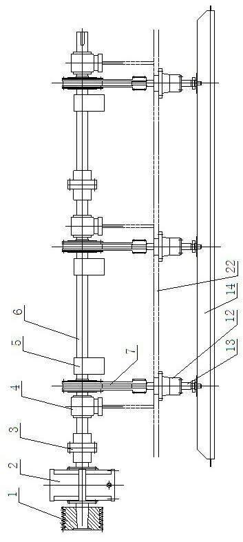
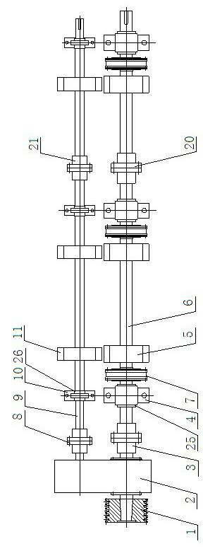
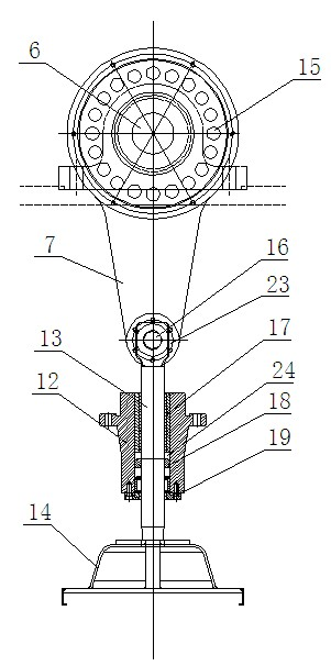
[0018] Such as figure 1 , 2 , 3, it is the main transmission mechanism of the medium-speed acupuncture machine, including a pulley 1, two camshafts 6 and two sub-spindles 9, two adjacent camshafts 6 are connected by the first coupling 20, adjacent The two sub-spindles 9 are connected by a second coupling 21 . The pulley 1 is connected to the transfer case 2, one output end of the transfer case 2 is connected to the camshaft 6 at the end through the main shaft coupling 3, and the other output end of the transfer case 2 is connected to the end camshaft through the countershaft coupling 8 The sub-spindle 9 is connected to the sub-spindle 9 and the camshaft 6 is arranged in parallel, the sub-spindle 9 and the camshaft 6 are arranged on the same side of the transfer case 2, and the rotation direction of the sub-spindle 9 and the camshaft 6 are opposite.

[0019] One to two vertically arranged connecting rods 7 are respectively arranged on each camshaft 6, and the upper end of eac...


PUM


Abstract

The invention relates to a main driving mechanism of an intermediate-speed needling machine and relates to the field of the structure of a needling machine. The main driving mechanism comprises a belt wheel and at least one cam wheel shaft; each cam wheel shaft is respectively provided with a main shaft weight balancing wheel; the main driving mechanism also comprises auxiliary main shafts the number of which equals to that of the cam wheel shafts; the belt wheel is connected with a transfer case; one output end of the transfer case is connected with the cam wheel shafts at the end part through a main shaft coupling, and the other output end of the transfer case is connected with the auxiliary main shafts at the end part through an auxiliary shaft coupling; the auxiliary main shafts and the cam wheel shafts are arranged in parallel, and are arranged at the same side of the transfer case, and the rotation directions of the auxiliary main shafts and the cam wheel shafts are opposite; each auxiliary main shaft is provided with auxiliary shaft weight balancing wheels the number of which equals to that of the main shaft weight balancing wheels; the auxiliary weight balancing wheels and the main shaft weight balancing wheels are arranged in one-to-one correspondence; and the auxiliary main shaft at one side of each auxiliary shaft weight balancing wheel is respectively connected with an auxiliary shaft bearing seat through a fourth bearing. According to the invention, the loading of the intermediate-speed needling machine can be born, the stress distribution is reasonable, and the cost of the intermediate-speed machine types is controlled effectively.

Description

technical field [0001] The invention relates to the structural field of acupuncture machines, in particular to the transmission system of medium-speed acupuncture machines. Background technique [0002] Needle punching nonwovens is the most common and extensive production method in the production process of nonwoven materials. Due to the characteristics of good permeability, excellent filtration performance and mechanical properties, needle-punched nonwovens are widely used in various industries such as geotechnical materials, filter materials, building waterproof materials, automotive interiors, synthetic leather substrates, and paper-making blankets. Non-woven fabric materials for daily use and daily use. Moreover, acupuncture nonwovens have many advantages such as simple processing technology, short process, flexible and convenient equipment combination, many types of products, wide application fields, less equipment investment, and short construction period. Therefore, ...

Claims


Application Information

Patent Timeline
Patent Type & Authority Applications(China)
IPC IPC(8): F16H37/00D04H18/00
CPCD04H18/02
Inventor 鞠永农王明霞徐祥
Owner JIANGSU YIZHENG HAIRUN TEXTILES MACHINERY
Learn More