Precision building template system

A technology for building formwork and formwork, which is applied in construction, building structure, formwork/formwork components, etc., can solve the problem of difficulty in ensuring the strength of internal joints, and achieve the goal of improving strength, preventing slurry leakage, and ensuring flatness. Effect

Active Publication Date: 2012-01-25
王亚运
View PDF6 Cites 13 Cited by
  • Summary
  • Abstract
  • Description
  • Claims
  • Application Information

AI Technical Summary

Problems solved by technology

[0005] For this reason, the first technical problem to be solved by the present invention is the problem that the strength of the inner seam of the plastic formwork in the prior art is difficult to guarantee during use; Assembled building formwork with grout leakage during pouring

Method used


Image

  • Precision building template system
  • Precision building template system
  • Precision building template system

Examples


Embodiment 1

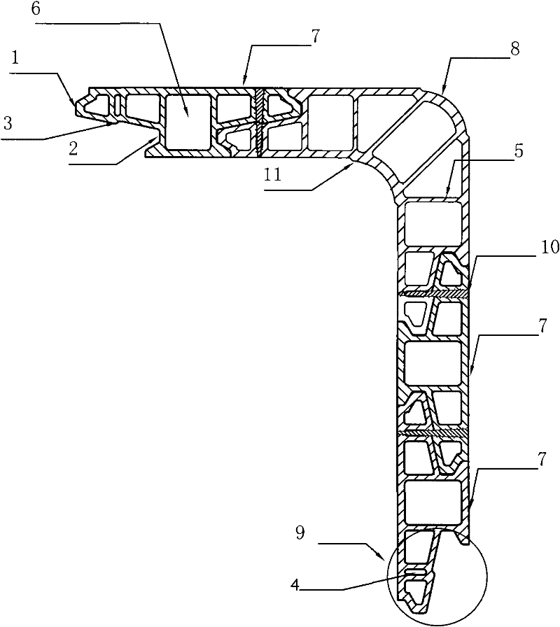
[0041] The building formwork that can be assembled according to the present invention is made up of several plane formwork 7 and corner piece formwork 8, and described plane formwork 7 and corner piece formwork 8 are all PVC materials, and the structure of described plane formwork 7 is as follows: figure 2 As shown, it can be seen from the figure that the planar formwork 7 has a symmetrical cross-section and has two panels, and a reinforcing rib is connected between the two panels, which is used to strengthen the planar formwork of the double-layer structure. 7 for structural connection and reinforcement; the planar template 7 has two splicing edges along the width direction that are respectively spliced ​​with adjacent templates, and a connector 9 is formed on the splicing edges. It can also be seen from the figure that the planar template 7 also includes a reinforcement accommodating hole 6 , and the reinforcement accommodating hole 6 is centrally arranged in the middle of t...

Embodiment 2

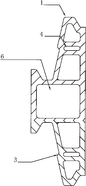
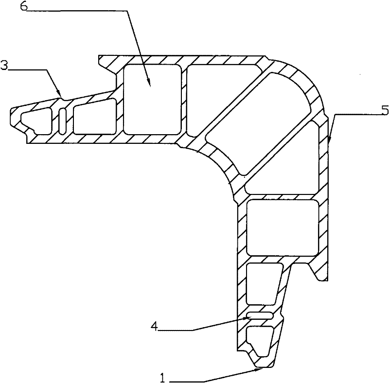
[0050] In this embodiment, the building formwork also includes the plane formwork 7 and corner fitting formwork 8. Compared with Embodiment 1, the corner fitting formwork 8 in this embodiment is at its corner Formed with rounded chamfers; in addition, in the above two templates in embodiment 1, no structure is provided on the transition surface between the chuck 1 and the slot 2. In this embodiment, the chuck 1 On the transition surface between the card slot 2 and the card slot 2, a card point 3 is formed. From the cross-section of the template, the shape of the card point 3 is that one side of the card head 1 protrudes from the card slot 3. Step shape on one side, the distance between the clamping point and the top surface of the clamping head is equal to the distance from the bottom surface of the clamping slot. In this way, after two adjacent planar formworks 7 or adjacent planar formworks 7 and corner fitting formworks 8 are plugged in, the clamping point 3 can be aligned ...

Embodiment 3

[0059] Under the condition that other conditions remain unchanged in the aforementioned Example 1 and Example 2 of the present invention, as a changeable embodiment, the shapes of the clip head 1 and the clip slot 2 of the building formwork of the present invention can also be selected It can be set to any shape that can be matched to realize insertion, as long as a card point can be formed between the card slot 2 and the card head 1 to realize self-fastening after insertion.

[0060] In this embodiment, a boss 11 protruding toward the side of the pouring material is also formed at the corner of the corner fitting formwork. When in use, it is not necessary to insert the self-tapping screws at all formwork joints after pouring. To disassemble, only need to dismantle the self-tapping screw at one of the sockets, that is, the boss 11 can be used as a supporting point to dismantle the template as a whole, which is very convenient to use.

[0061] Apparently, the above-mentioned em...


PUM


Abstract

The invention discloses a spliceable precision building template system which is provided with two panels and reinforced ribs for connecting the two panels, wherein connecting heads (9) are formed on the splicing sides spliced with adjacent templates; seen from the cross section of the template, each connecting head (9) comprises a chuck (1) protruding towards the adjacent template, a clamping groove (2) and a connecting mechanism (4); the clamping groove (2) is inwards concaved relative to the protruding direction of the chuck (1); the connecting heads (9) of the adjacent templates are combined together by using the connecting mechanism (4); and the chuck (1) is suitably embedded into the clamping groove (2); and outer surfaces of the panels at two sides of the adjacent templates are positioned on the same plane at the same side. The building template with the structure can be freely spliced; after splicing, a joint is tight and favorable integrity is achieved; and after grouting, the probability of slurry leakage is low.

Description

technical field [0001] The invention relates to the technical field of building construction, in particular to an assembleable precision building formwork system. Background technique [0002] In the prior art, the materials of construction formwork mainly include wood, steel and plastic. The construction formwork of the above materials has some shortcomings that are difficult to overcome. For example, the formwork made of wooden materials will be damaged after use. Breakage and deformation occur, and usually cannot be reused, which makes the cost higher, and the wooden material formwork has poor erosion resistance. After encountering rainwater or water in the concrete during use, the wooden material building formwork is also prone to deformation, resulting in the loss of the formwork. The accuracy is destroyed; in addition, the manufacture of the above-mentioned wooden material building formwork needs to cut down a large amount of forest resources, which seriously damages t...

Claims


Application Information

Patent Timeline
Patent Type & Authority Applications(China)
IPC IPC(8): E04G9/05E04G17/02
Inventor 王亚运
Owner 王亚运
Why Eureka
Try Eureka