Thrust structure of engine cam shaft

A technology for camshafts and engines, applied in the directions of engine components, machines/engines, connecting components, etc., can solve the problems of insufficient structure, increase the size of the blank, increase the difficulty of manufacturing, etc., so as to reduce the overall diameter and reduce the blank. Size, the effect of saving thickness and space

Active Publication Date: 2013-06-05
WUXI KIPOR POWER CO LTD
View PDF4 Cites 0 Cited by
  • Summary
  • Abstract
  • Description
  • Claims
  • Application Information

AI Technical Summary

Problems solved by technology

[0002] At present, the known engine camshaft thrust structure is that one end of the camshaft is provided with an annular protrusion, the annular protrusion is stuck on the outer end surface of the body, a thrust plate is covered on the annular protrusion, and then the thrust plate is locked. On the engine block, thereby limiting the movement of the camshaft in the axial direction relative to the block
This kind of thrust structure is simple, compact, and more general, but setting the ring-shaped protrusion on the camshaft will increase the size of the blank and increase the difficulty of manufacturing; The increase, the structure is not streamlined enough

Method used


Image

  • Thrust structure of engine cam shaft

Examples


Embodiment Construction

[0011] The present invention will be further described below in conjunction with specific drawings and embodiments.

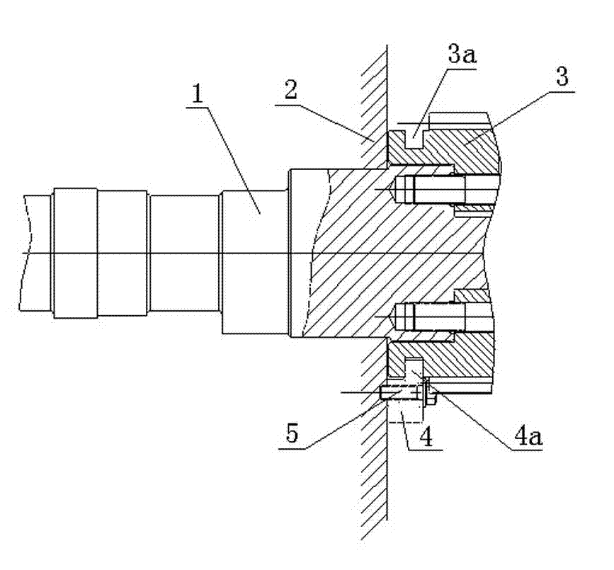
[0012] Such as figure 1 As shown, the camshaft 1 is installed on the engine body 2, the gear 3 is installed on the outer end of the camshaft 1, and the outer circumference of the gear 3 near the end of the engine body 2 is provided with an annular groove 3a; the thrust plate 4 is fixed on the engine body by bolts 5 2, the thrust plate 4 is provided with a positioning lip 4a that is snapped into the annular groove 3a, so that the thrust plate 4 fixed on the engine body 2 limits the relative movement of the camshaft 1 in the axial direction. Movement of the engine block 2.

[0013] Such as figure 1 As shown, the side of the positioning convex edge 4a of the thrust plate 4 corresponding to the annular groove 3a is concave arc-shaped, so as to adapt to the shape of the annular groove 3a. An oil channel is opened in the thrust plate 4, and the oil channel is used...


PUM


Abstract

An engine camshaft thrusting structure. A camshaft (1) is arranged on an engine block (2). A gear (3) is arranged on an outer end of the camshaft (1). An annular groove (3a) is provided on the periphery of the gear (3) close to the engine block (2). A thrust plate (4) is fixed on the engine block (2). Arranged on the thrust plate (4) is a positioning nosing (4a) for snapping into the annular ring (3a). The camshaft thrusting structure allows for reduced overall diameter of the camshaft, thus allowing for reduced blank size, and for reduced manufacturing difficulty. While at the same time, because an annular protrusion of the camshaft is obviated, the space for the thickness of the thrust plate is conserved, this allows for reduced distance between an end face of the camshaft and the engine block, thus for reduced size of the entire engine.

Description

technical field [0001] The invention belongs to the technical field of engines, and in particular relates to a thrust structure for limiting axial movement of an engine camshaft relative to an engine body. Background technique [0002] At present, the known engine camshaft thrust structure is that one end of the camshaft is provided with an annular protrusion, the annular protrusion is stuck on the outer end surface of the body, a thrust plate is covered on the annular protrusion, and then the thrust plate is locked. On the body of the engine, the movement of the camshaft relative to the body in the axial direction is limited. This kind of thrust structure is simple, compact, and more general, but setting an annular protrusion on the camshaft will increase the size of the blank and increase the difficulty of manufacturing; The increase, the structure is not streamlined enough. Contents of the invention [0003] The purpose of the present invention is to overcome the sho...

Claims


Application Information

Patent Timeline
Patent Type & Authority Patents(China)
IPC IPC(8): F16B21/10F16H57/04
CPCF16B9/023F01L1/047F01L2001/0476F16B9/056
Inventor 肖亨琳尤良盛
Owner WUXI KIPOR POWER CO LTD
Why Eureka
Try Eureka