Transformer substation local discharging signal online monitoring and positioning method

A discharge signal and positioning method technology, applied in the direction of measuring electricity, measuring devices, fault locations, etc., can solve the problems of time-consuming, affecting the work efficiency of substation personnel, testing principles, and different detection accuracy of test items, etc., to achieve shortening Power outage time, easy maintenance effect

Active Publication Date: 2012-01-25
STATE GRID CORP OF CHINA +1
View PDF3 Cites 28 Cited by
  • Summary
  • Abstract
  • Description
  • Claims
  • Application Information

AI Technical Summary

Problems solved by technology

[0004] 1. Partial discharge faults may occur in any high-voltage power equipment in the substation. If you want to monitor the primary electrical equipment in the whole station, you need to install a partial discharge monitoring device on each equipment, which takes a lot of time and effort. Financial resources for equipment procurement and installation;
[0005] 2. The test principles, test items, and detection accuracy of each monitoring system are not the same, and the processing and analysis of a large number of test data will directly affect the work efficiency of substation personnel;
[0006] 3. The maintenance and management of many monitoring devices also takes a lot of time and manpower

Method used


Image

  • Transformer substation local discharging signal online monitoring and positioning method
  • Transformer substation local discharging signal online monitoring and positioning method
  • Transformer substation local discharging signal online monitoring and positioning method

Examples


Embodiment Construction

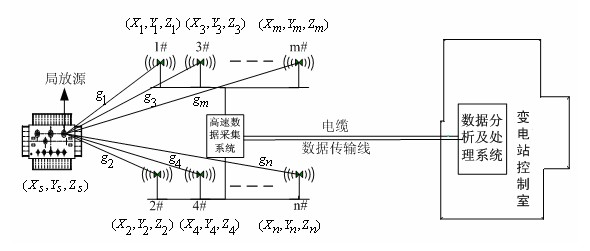
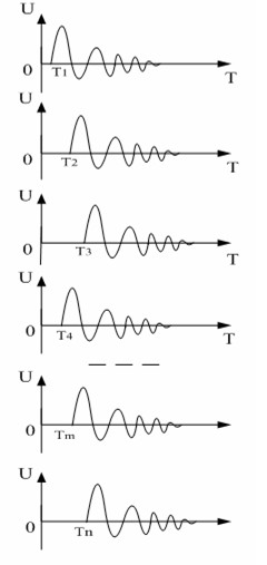
[0027] Such as figure 1 As shown, assuming that the spatial coordinate of the local discharge source is (X S , Y S ,Z S ), each antenna in the antenna array also has its own space coordinates, each antenna 1#, 2#, 3#, 4#...m#, n# in the antenna array can receive the signal from the local discharge source , The high-speed data acquisition system collects the signals received by each antenna (such as figure 2 (Shown) are then transmitted to the data analysis and processing system through each independent data transmission channel. After the data analysis and processing system filters these signals, once it finds a partial discharge signal, it will immediately locate the partial discharge source.

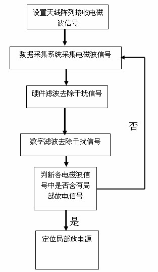
[0028] Such as image 3 As shown, in this embodiment, the following steps are used to perform online monitoring and positioning of partial discharge signals in substations:

[0029] (1) An antenna array is set up near the center of the substation space area, and the antenna array is used ...


PUM


Abstract

The invention discloses a transformer substation local discharging signal online monitoring and positioning method. Different from the traditional local discharging monitoring method which only can be used for monitoring one power equipment, the method provided by the invention is used for carrying out online monitoring and positioning on the local discharging signals of all the power equipment in a transformer substation. The method comprises the following steps of: (1) arranging an antenna array close to a central position in a space region of the transformer substation, and receiving an electromagnetic signal in the transformer substation by adopting the antenna array; (2) acquiring electromagnetic wave signals received by all antennae; (3) filtering the acquired electromagnetic wave signals, comparing the filtered electromagnetic wave signals with a standard local discharging signal; if the filtered electromagnetic wave signals are similar to or same with the standard local discharging signal, judging that a local discharging source exists in the substation; and (4) positioning the local discharging source by utilizing time difference of the local discharging signals received by two different antennae.

Description

Technical field [0001] The invention relates to an electrical signal monitoring and positioning method, in particular to a method for monitoring and locating insulation faults in a substation. Background technique [0002] Insulation failure is one of the main faults in the operation of power equipment. Before the insulation failure of power equipment, there will generally be a gradual partial discharge process, which will eventually lead to insulation breakdown. If partial discharge monitoring and diagnosis of operating equipment can be carried out in this process, partial discharge signals can be found in time, and defects can be dealt with in advance, and insulation breakdown faults can be effectively avoided. In addition, the positioning of the location of the partial discharge also helps to formulate more targeted maintenance and treatment programs, reduce power outage time and improve maintenance efficiency. [0003] Therefore, many scientific researchers at home and abroad ...

Claims


Application Information

Patent Timeline
Patent Type & Authority Applications(China)
IPC IPC(8): G01R31/02G01R31/08
Inventor 苗培青李秀卫慕世友姚金霞辜超云玉新
Owner STATE GRID CORP OF CHINA
Why Eureka
Try Eureka