Method, apparatus, and program for aligning images
A technology for aligning devices and images, which is applied in image enhancement, image analysis, image data processing, etc., can solve the problems of artifacts in subtraction images, and achieve high-accuracy results
Inactive Publication Date: 2012-01-25
FUJIFILM CORP
8 Cites 1 Cited by
AI-Extracted Technical Summary
Problems solved by technology
If a positional shift occurs in the heart in this way, there will be arti...
Method used
[0089] In this way, the first embodiment generates a plurality of first band images and a plurality of second band images representing structures of different frequency bands for each of the first radiographic image Sa and the second radiographic image Sb. image. Next, a position offset is obtained for the first and second band images, and the second band image is deformed based on the position shift to positionally align the first and second band images. Next, the deformed second band image is reconstructed to generate a deformed radiographic image Sb′. Here, in the case where a plurality of structures of different frequency bands are included in the first and second radiographic images and the plurality of structures respectively exhibit different three-dimensional motions, the positional shift amount of each frequency band is that of the structures in each frequency band position offset. Thus, positional alignment is performed on the band-domain images of each frequency band by using the position offset, so as to positionally align the structure of each frequency band. As a result, positional alignment of the structure of each frequency band can be achieved with high precision. Therefore, the soft tissue image SP and bone image BP generated by the energy subtraction process using...
Abstract
A band image generating means generates a plurality of first band images and a plurality of second band images that represent structures of different frequency bands within a first and a second image of the same portion of a single subject. A positional shift amount obtaining means obtains amounts of positional shift among corresponding positions within the first band images and the second band images of corresponding frequency bands.
Application Domain
Image enhancementImage analysis +2
Technology Topic
Frequency bandImage representation
Image
Examples
- Experimental program(1)
Example Embodiment
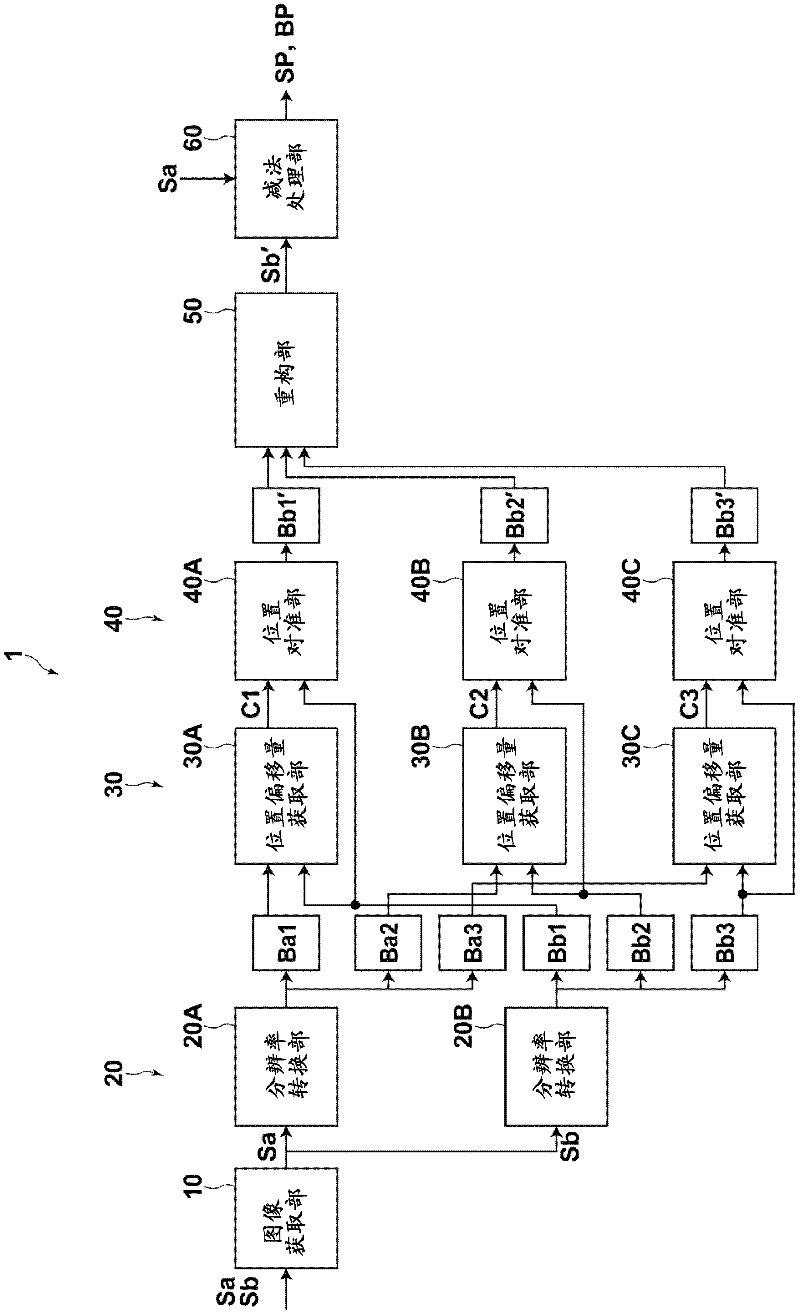
[0061] Hereinafter, embodiments of the present invention will be described with reference to the drawings. figure 1 It is a block diagram showing the schematic structure of the image positioning device 1 according to the first embodiment of the present invention. note, figure 1 The image positioning device 1 in is applied to an energy subtraction device that uses a pair of radiation images to perform subtraction processing. For example, the energy subtraction device is installed on an imaging console that uses a radiation detector to obtain radiation images. By executing the image alignment processing program of the auxiliary storage device downloaded to the computer (such as a personal computer), such as figure 1 The structure of the image position alignment device 1 is shown. At this time, the image alignment processing program is installed in the computer after being distributed by recording on a data recording medium such as a CD-ROM or via a network such as the Internet.
[0062] The image position alignment device 1 according to the first embodiment is equipped with: an image acquisition section 10; a resolution conversion section 20; a position shift amount acquisition section 30; a position alignment section 40; a reconstruction section 50; and a subtraction processing section 60 .
[0063] The image acquisition unit 10 acquires a first radiation image Sa and a second radiation image Sb to be aligned with each other. Examples of the first radiation image Sa and the second radiation image Sb include a high-energy image and a low-energy image acquired by two imaging operations using rays having different energies. Here, for example, during the frontal chest imaging operation, the high-energy image is acquired by the imaging operation during the application of the tube voltage ranging from 100KVp to 140KVp to the radiation source, and the low-energy image is obtained by applying the tube voltage from 50KVp to the radiation source. It was acquired during imaging operation with tube voltage in the range of 80KVp. Note that high-energy images can be used as-is for image diagnosis. As another option, the first radiation image Sa and the second radiation image Sb may be two radiation images in a time series of the same part of a single subject acquired at different times to be used in the time subtraction process.
[0064] The resolution conversion unit 20 converts the resolutions of the first radiation image Sa and the second radiation image Sb into a plurality of band images of different frequency bands. Note that in figure 1 Among them, the resolution conversion section 20 is equipped with a first resolution conversion section 20A for converting the resolution of the first radiation image Sa, and a second resolution conversion section 20B for converting the resolution of the second radiation image Sb. Alternatively, the single resolution conversion section 20 may convert the resolution of both the first radiation image Sa and the second radiation image Sb. In the following description, the term "resolution conversion section 20" collectively refers to the first resolution conversion section 20A and the second resolution conversion section 20B.
[0065] figure 2 It is a diagram for explaining resolution conversion. It should be noted here that only a description of the resolution conversion of the first radiation image Sa is given. However, the same resolution conversion processing is performed on the second radiation image Sb. First, the resolution conversion section 20 uses a Gaussian filter of σ=1 to perform filtering processing on the radiographic image Sa to reduce the radiographic image Sa to 1/2 of its size and generate a reduced image Ssa1. Next, the resolution conversion section 20 generates an enlarged image Ssa1' having the same size as the radiation image Sa from the reduced image Ssa1 by using an interpolation operation such as cubic spline interpolation. Next, the enlarged image Ssa1' is subtracted from the radiographic image Sa to generate a first band image Ba1. Next, the resolution conversion section 20 uses a Gaussian filter of σ=1 to perform filtering processing on the reduced image Ssa1 to reduce the reduced image Ssa1 to 1/2 of its size and produce a reduced image Ssa2. Next, the resolution conversion section 20 generates an enlarged image Ssa2' having the same size as the enlarged image Ssa1' from the reduced image Ssa2 to generate an enlarged image Ssa2'. Next, the enlarged image Ssa2' is subtracted from the enlarged image Ssa1' to generate a second band image Ba2. Further, the above-mentioned processing is repeated until a band image of a desired frequency band is generated, thereby generating a plurality of band images Baj (j=1 to n) of a plurality of frequency bands. Note that other resolution conversion techniques such as wavelet transform can be used to generate multiple band images Baj. As a further option, the multiple band images of different frequency bands may be generated by the following filtering process: the filtering process reduces the high frequency part in the image without changing the size of the radiographic image.
[0066] In the present embodiment, three band images Ba1 to Ba3 are generated at one level Bb1 to Bb3 for the first radiation image Sa and the second radiation image Sb. However, a larger number of band images of different frequency bands can be generated.
[0067] The position shift amount acquisition section 30 acquires the position shift amounts of corresponding pixel positions of the first band images Ba1 to Ba3 and the second band images Bb1 to Bb3 having corresponding frequency bands. For example, template matching is performed in the first band images Ba1 to Ba3 and the second band images Bb1 to Bb3 with corresponding frequency bands, and the position offset between the corresponding pixel positions is calculated for the first and second band images C1 to C3. Here, the calculation processing using the positional shift amount of the first band image Ba1 and the second band image Ba2 is described. Such as image 3 As shown, the ROI (region of interest) is set at the corresponding grid points in the first band image Ba1 and the second band image Bb1. One of the ROIs (for example, the ROI in the first band image Ba1) is offset within a predetermined range using the corresponding ROI in the second band image Bb1 as a reference to calculate the similarity between the two ROIs degree. Next, the points in the second band image Bb1 corresponding to the grid points in the first band image Ba1 when the degree of similarity is the largest are obtained. After that, the distance between the grid points in the second band image Bb1 and the corresponding points is calculated as the position shift amount C1. Note that the position offset for the pixel position between the grid points is calculated by using the interpolation operation of the position offset of the grid position. As an option, a vector connecting the grid points to the corresponding points can be used as the position offset.
[0068] Note that a normalized cross-correlation value can be used to express the similarity. In addition, in image 3 In the example shown, the number of ROIs is set to four, but the present invention is not limited to this structure. Furthermore, ROI can not only be image 3 It is set on a grid point as shown, and it may also be set on a feature point in the image, for example, the intersection of the edges included in the first band images Ba1 to Ba3 and the second band images Bb1 to Bb3.
[0069] Here, for example, a technique such as that disclosed in Japanese Patent Laid-Open No. 2000-342558 may be employed to calculate the normalized cross-correlation value. When the pixel value of the i-th pixel in the ROI of the first band image is designated as Sa(i) and the pixel value of the i-th pixel in the ROI of the second band image is designated as Sb(i), The normalized cross-correlation value can be calculated according to the following formula (1). Note that I represents the total number of pixels in the ROI, m A And m B Respectively represent the average pixel value in the ROI of the first and second band images, and σ A And σ B These are the standard deviations of the pixel values in the ROI of the first and second band images, respectively.
[0070] C = 1 i X i = 1 I [ Sa ( i ) } - m A { Sa ( i ) } - m B } σ A · σ B - - - ( 1 )
[0071] m A = 1 I X i = 1 I Sa ( i )
[0072] m B = 1 I X i = 1 I Sb ( i )
[0073] σ A = 1 I X i = 1 I { Sa ( i ) - m A } 2
[0074] σ B = 1 I X i = 1 I { Sb ( i ) - m B } 2
[0075] By adopting the normalized cross-correlation value in this way, the second image can be calculated without being affected by the average density or grayscale difference (which is caused by the difference in exposure conditions between the first and second images) The similarity between the first and second band images. Here, there is a position shifted region between the first and second band images, and the correlation between the first and second band images is very low. Therefore, when the ROIs of the corresponding first and second band images are completely matched, the normalized cross-correlation value takes the value 1, and when they are completely independent of each other, the value is 0.
[0076] Note that in figure 1 In the above, the image positioning device 1 is equipped with a first position shift amount acquiring unit 30A for acquiring the position shift amount C1 between the band images Ba1 and Bb1, and a first position shift amount acquiring unit 30A for acquiring the position between the band images Ba2 and Bb2. The second position shift amount acquisition unit 30B of the shift amount C2 and the third position shift amount acquisition section 30C for acquiring the position shift amount C3 between the band images Ba3 and Bb3. Alternatively, the single position shift amount acquisition section 30 may be configured to acquire the position shift amounts C1 to C3 between the first band images Ba1 to Ba3 and the second band images Bb1 to Bb3. In the following description, the term "positional shift amount acquisition unit 30" is a collective term for the first to third positional shift amount acquisition sections 30A to 30C.
[0077] The method by which the position shift amount acquiring section 30 acquires the position shift amount is not limited to the method described above. Alternatively, the method disclosed by H. Fujiyoshi in "Gradient Based Feature Extraction-SIFT and HOG", Reports of the Academy of Data Processing CVIM 160, pages 211-224, 2007 can be used. This method uses Scale Invariant Feature Transform (SIFT) or Histograms of Oriented Gradients (HOG) to detect feature points in the image to be aligned, where SIFT describes the rotation, There is no change in the scale change and so on. HOG is the direction of the brightness gradient in the local area in the form of a histogram. In this case, the position offset acquisition unit 30 uses the method disclosed by Fujiyoshi to detect the feature points in the first band image Ba1, and detects the points corresponding to the feature points in the second band image Bb1, and Calculate the position offset between the characteristic point and its corresponding point.
[0078] As another alternative solution, the first radiation image Sa and the second radiation image Sb may be used to obtain the position offset. In this case, the positional offset between the corresponding pixel positions in the first radiographic image Sa and the second radiographic image Sb can be used as the difference between the first band images Ba1 to Ba3 and the second band images Bb1 to Bb3. The position offset between.
[0079] Preferably, when acquiring the position offset, the position offset is first calculated for the band image with the lowest frequency band, and then the position offset is calculated for the band image with the next lowest frequency band. In the case of calculating the position offset of the band image with the next lowest frequency band, when template matching is performed using the position offset calculated for the lower frequency band, calculating the position offset in this way makes the ROI search The range narrows. Therefore, the position shift amount can be calculated more efficiently.
[0080] The positioning unit 40 uses, for example, a technique disclosed in Japanese Patent Application Laid-Open No. 2001-218110 in which nonlinear distortion transformation (warping) is performed on a pair of a plurality of pairs of images, and the first band image Ba1 To Ba3 and the second band images Bb1 to Bb3 perform positional alignment. In the current embodiment, the offsets of the grid points in the second band image relative to the grid points in the first band image are calculated as the position offset amounts C1 to C3. Therefore, by deforming the second band images Bb1 to Bb3, the first band images Ba1 to Ba3 and the second band images Bb1 to Bb3 are aligned in position.
[0081] note, figure 1 The image positioning device 1 in the is equipped with: a first positioning part 40A for positioning the band images Ba1 and Bb1; a second position for positioning the band images Ba2 and Bb2 Aligning part 40B; and a third position aligning part 40C for aligning the band images Ba3 and Bb3. Alternatively, a single position aligning part 40 may align the positions of the first band images Ba1 to Ba3 and the second band images Bb1 to Bb3. In the following description, the term "image alignment section 40" is a collective term for the first image alignment section 40A to the third image alignment section 40C.
[0082] As an alternative to twisting, affine transformation accompanied by parallel movement, rotation, enlargement and reduction, or one of parallel movement, rotation, enlargement and reduction can be used to align the first and second belts in position Domain image. Especially in the case where the radiographic image does not include a structure such as the heart that exhibits a large motion, the positional alignment by affine transformation or one of parallel movement, rotation, enlargement, and reduction can shorten the calculation required compared with distortion. The amount of time.
[0083] The reconstruction section 50 reconstructs the second band images Bb1 ′ to Bb3 ′ deformed by the position alignment section 40 to generate a deformed second radiation image Sb ′. Specifically, execution and figure 2 The shown resolution conversion process is reversed to reconstruct the second band images Bb1' to Bb3' and generate the deformed second ray image Sb'. Note that you can execute in the reverse order by figure 2 Processing to achieve reconstruction. That is, the enlarged image Ssb3' is added to the band image Bb3' to produce a reduced image Ssb2, and then the reduced image Ssb2 is enlarged to produce an enlarged image Ssb2". Next, the enlarged image Ssb2" The image Ssb2" is added to the band image Bb2' to generate a reduced image Ssb1, and then the reduced image Ssb1 is enlarged to generate an enlarged image Ssb1". After that, the enlarged image Ssb1" is added to the band image Bb1' to generate a deformed second radiation image Sb'. Note that in the case where the second band images Bb1 to Bb3 are obtained through wavelet transform, reconstruction is achieved by adopting inverse wavelet transform.
[0084] The subtraction processing unit 60 uses the first radiographic image Sa and the deformed second radiographic image Sb′ to perform subtraction processing to obtain a soft tissue image SP representing the soft tissue of the subject from which bones are removed, and a soft tissue image SP representing the subject’s The skeleton image BP of the skeleton. Generally, the differential image Psub represents the corresponding pixel in the first radiation image Sa (high energy image) multiplied by the first weighting coefficient Ka and the second radiation image Sb (low energy image) multiplied by the second weighting coefficient Kb The difference between and can be expressed by equation (2). Note that in equation (2), Kc represents a predetermined offset value.
[0085] Psub=Ka·Sa-Kb·Sb’+Kc (2)
[0086] The subtraction processing section 60 performs the calculation in the formula (2) to generate the soft tissue image SP as the difference image Psub. Hereinafter, the subtraction processing unit 60 subtracts the soft tissue image SP from the first radiation image Sa to generate a bone image BP (BP=Sa-SP).
[0087] Next, the steps of this processing executed by the first embodiment are described. Figure 4 It is a flowchart showing the procedure of the processing executed by the first embodiment. First, the image acquiring unit 10 acquires the first radiation image Sa and the second radiation image Sb (image acquisition, step ST1). Next, the resolution conversion unit 20 converts the resolution of the first radiation image Sa and the second radiation images Sa and Sb into a plurality of band images of different frequency bands to generate bands for the first radiation image Sa and the second radiation image Sb The domain images Ba1 to Ba3 and Bb1 to Bb3 (step ST2). Next, the position shift amount acquisition section 30 acquires the position shift amounts C1 to C3 between the first band images Ba1 to Ba3 and the second band images Bb1 to Bb3 (step ST3). The position alignment section 40 deforms the second band images Bb1 to Bb3 based on the position shift amounts C1 to C3 to perform position alignment of the second band images Bb1 to Bb3 with respect to the first band images Ba1 to Ba3 (step ST4). The reconstruction section 50 reconstructs the deformed second band images Bb1' to Bb3' to generate the deformed second radiation image Sb' (step ST5).
[0088] Next, the subtraction processing section 60 uses the first radiographic image Sa and the deformed second radiographic image Sb′ to perform subtraction processing to obtain a soft tissue image SP representing the soft tissue of the subject from which bones are removed, and a soft tissue image SP representing the subject’s soft tissue. The skeleton image BP of the skeleton of the body (step ST6), and the process ends.
[0089] In this way, the first embodiment generates a plurality of first band images and a plurality of second band images representing structures of different frequency bands for each of the first radiation image Sa and the second radiation image Sb. Next, the position offset amount is acquired for the first and second band images, and the second band image is deformed based on the position offset amount to align the first and second band images in position. Next, the deformed second zone image is reconstructed to generate the deformed radiographic image Sb'. Here, in the case where the first and second ray images include multiple structures in different frequency bands, and the multiple structures respectively exhibit different three-dimensional motions, the position offset of each frequency band is the amount of structure in each frequency band. The position offset. As a result, the positional offset is used to position the band image of each frequency band, so as to position the structure of each frequency band. As a result, it is possible to achieve positional alignment of the structure of each frequency band with high accuracy. Therefore, the soft tissue image SP and the bone image BP generated by the energy subtraction process using the first radiation image Sa and the deformed second radiation image Sb′ have no artifacts, and the image quality is high.
[0090] Especially in the case where the radiographic image is an image of the chest region of the human body, the heart is a relatively low-frequency structure, while the pulmonary blood vessels are a relatively high-frequency structure. According to the first embodiment, position alignment is performed between band image pairs each having a different frequency band. Therefore, the heart and lung blood vessels are aligned separately. Thus, even if the heart and pulmonary blood vessels included in the first radiographic image Sa and the second radiographic image Sb exhibit different motions, respectively, the soft tissue image SP and the bone image BP can be generated by using the deformed second radiographic image Sb′ Without artifacts.
[0091] Next, a second embodiment of the present invention will be described. Figure 5 It is a block diagram showing a schematic structure of an image positioning apparatus 1A according to the second embodiment of the present invention. Note that the same reference numerals are used to denote the same elements in the second embodiment as those in the first embodiment, and a detailed description thereof is omitted unless it is particularly necessary. The image positioning device 1A of the second embodiment is different from the image positioning device 1 of the first embodiment in that it is equipped with a deformed component calculation section 70 that calculates the deformed second band image Bb1 The differences between the corresponding pixels in the second band images Bb1 to Bb3 before the deformation and the second band images Bb1 to Bb3 before the deformation are used as the deformed component band images D1 to D3; the reconstruction unit 52 reconstructs the deformed component band images D1 to D3 D3 to generate a deformed component image Db; and a subtracting section 80 that subtracts the deformed component image Db from the second radiation image Sb to calculate a deformed second radiation image Sb'.
[0092] Note that in Figure 5 , The image positioning device 1A is equipped with: a first deformation component calculation unit 70A for calculating the deformation component band image D1; a second deformation component calculation unit 70B for calculating the deformation component band image D2; and The third deformed component calculation unit 70C that calculates the deformed component band image D3. Alternatively, a single deformation component calculation section 70 may be configured to calculate the deformation component band images D1 to D3. In the following description, the term "deformation component calculation unit 70" is a collective term for the first to third deformation component calculation units 70A to 70C.
[0093] Next, the steps of the processing performed by the second embodiment will be described. Image 6 It is a flowchart showing the procedure of the processing executed by the second embodiment. note, Image 6 The processing from step ST11 to step ST14 in the flowchart and Figure 4 The processing from step ST1 to step ST4 in the flowchart of is the same. Therefore, its detailed description is omitted.
[0094] After step ST14, the deformed component calculation section 70 calculates the difference between the corresponding pixels in the second band images Bb1 to Bb3 and the deformed second band images Bb1' to Bb3' to generate the deformed component band images D1 to Bb3'. D3 (step ST15). Next, the reconstruction section 52 reconstructs the deformed component band images D1 to D3 to generate the deformed component image Db (step ST16). The deformed component image Db is an image that only represents the components included in the second radiation image Sb that are deformed with respect to the first radiation image Sa.
[0095] Next, the subtracting section 80 subtracts the pixels corresponding to the pixels in the second radiation image Sb in the deformed component image Db from the second radiation image Sb to remove the second radiation image Sb from the second radiation image Sb The deformed component of the first radiation image Sa is generated, and the deformed second radiation image Sb' is generated (step ST17). Next, the subtraction processing section 60 uses the first radiographic image Sa and the deformed second radiographic image Sb' to perform subtraction processing to generate a soft tissue image SP representing the soft tissue of the subject from which bones have been removed, and a soft tissue image SP representing the soft tissue of the subject. The skeleton image BP of the skeleton of the specimen (step ST18), and this process ends.
[0096] Here, the deformation component image Db generated in the second embodiment represents the positional shift amount of the structure of the different frequency bands included in the first radiation image Sa and the second radiation image Sb. For this reason, even in the case where the first and second radiographic images contain a plurality of structures in different frequency bands and the plurality of structures respectively exhibit different three-dimensional motions, by subtracting the deformation component image Db from the second radiographic image Sb It is also possible to substantially align the first radiation image Sa and the second radiation image Sa for each pair of the first band image and the second band image of different frequency bands. Thereby, even if the frequency bands of the structures included in the first and second radiographic images are different, it is possible to realize the positional alignment of the structures of each frequency band with high accuracy. As a result, the soft tissue image SP and the bone image BP generated by the energy subtraction process using the first radiographic image Sa and the deformed second radiographic image Sb' have no artifacts, and the image quality is high.
[0097] Next, a third embodiment of the present invention will be described. Figure 7 It is a block diagram showing a schematic structure of an image positioning apparatus 1B according to the third embodiment of the present invention. Note that the same reference numerals are used to denote the same elements in the third embodiment as those in the first embodiment, and a detailed description thereof is omitted unless it is particularly necessary. The image positioning device 1B of the third embodiment is different from the image positioning device 1 of the first embodiment in that it is equipped with a band image subtraction processing unit 90 that uses first band images Ba1 to Ba3 and the deformed second band images Bb1' to Bb3' perform subtraction processing; and a reconstruction section 54 which reconstructs the band images of bones and soft tissues generated by the subtraction processing section 90 to generate soft tissue images SP and bones Image BP.
[0098] Note that in Figure 7 , The image positioning device 1B is equipped with: a first band image subtraction processing unit 90A for calculating the soft tissue band image SP1 and the bone band image BP1; and for calculating the soft tissue band image SP2 and the bone band image BP2 The second band image subtraction processing unit 90B; and the third band image subtraction processing unit 90C for calculating the soft tissue band image SP3 and the bone band image BP3. Alternatively, a single band image subtraction processing section 90 may be constructed to calculate the soft tissue band images SP1 to SP3 and the bone band images BP1 to BP3. In the following description, the term "band image subtraction processing unit 90" is a collective term for the first band image subtraction processing unit 90A to the third band image subtraction processing unit 90C.
[0099] Next, the steps of processing performed by the third embodiment will be described. Figure 8 It is a flowchart showing the processing procedure performed by the third embodiment. note, Figure 8 The processing from step ST21 to step ST24 in the flowchart and Figure 4 The processing from step ST1 to step ST4 in the flowchart of is the same. Therefore, its detailed description is omitted.
[0100] After step ST24, the band image subtraction processing section 90 uses the first band images Ba1 to Ba3 and the deformed second band images Bb1' to Bb3' to perform subtraction processing to generate soft tissue band images SP1 to SP3 and bones Band images BP1 to BP3 (step ST25). Next, the reconstruction section 54 reconstructs the soft tissue zone images SP1 to SP3 and the bone zone images BP1 to BP3 to generate the soft tissue image SP and the bone image BP (step ST26), and the process ends.
[0101] Here, the soft tissue band images SP1 to SP3 and the bone band images BP1 to BP3 obtained by performing subtraction processing using the first band images Ba1 to Ba3 and the deformed second band images Bb1' to Bb3' represent soft tissue images And the frequency components of the bone image, from which the positional offset between the structures of the various frequency bands has been removed. For this reason, by reconstructing the soft tissue image SP from the soft tissue zone images SP1 to SP3 and the bone image BP from the bone zone images BP1 to BP3 as in the third embodiment, it is possible to generate the soft tissue image SP and bones without artifacts. Image BP.
[0102] Next, a fourth embodiment according to the present invention will be described. Picture 9 It is a block diagram showing a schematic structure of the image position alignment apparatus 100 according to the fourth embodiment of the present invention. Such as Picture 9 As shown, the image position alignment device 100 of the fourth embodiment is equipped with: an image acquisition section 110; a structure decomposition section 120; a position shift amount acquisition section 130; a position alignment section 140; an addition synthesis section 150; and a subtraction processing section 160. Note that in the fourth embodiment, the time subtraction processing is performed using the first radiation image Sa and the second radiation image Sb. Therefore, the two radiographic images Sa and Sb are time-series images acquired at different times.
[0103] The processing performed by the image acquisition unit 110 is the same as the processing performed by the image acquisition unit 10 in the first to third embodiments.
[0104] The structure decomposition section 120 decomposes each of the first radiation image Sa and the second radiation image Sb into a plurality of structure images, which represent structures including different anatomical features. Note that in the fourth embodiment, the first radiographic image Sa and the second radiographic image Sb are decomposed into a bone image representing bones and a soft tissue image representing soft tissue. For example, the radiographic image can be decomposed into a bone image and a soft tissue image by the technique disclosed in the published US Patent Application No. 2005/0100208. This technology uses a neural network that has been learned to generate bone images by extracting bones from radiographic images including bones and soft tissues to generate bone images from radiographic images. The structure decomposition unit 120 uses the technology disclosed in the published US Patent Application No. 2005/0100208 to generate a first skeletal image SaB from the first radiographic image Sa, and subtract the first skeletal image SaB from the first radiographic image Sa , To generate the first soft tissue image SaS. Similarly, the second skeletal image SbB is generated from the second radiographic image Sb, and the second soft tissue image SbS is generated by subtracting the second skeletal image SbB from the second radiographic image Sb.
[0105] Note that in Picture 9 Here, the image positioning apparatus 100 is equipped with: a first structure decomposition part 120A that decomposes the structure in the first radiation image Sa; and a second structure decomposition part 120B that decomposes the structure in the second radiation image Sb. Alternatively, a single structure decomposition part 120 may be constructed to decompose the structures in the first and second radiation images Sa and Sb. In the following description, the term "structural decomposition part 120" is a collective term for the first structural decomposition part 120A and the second structural decomposition part 120B.
[0106] The position shift amount acquiring unit 130 acquires the position shift amount C11 between the corresponding positions in the first skeletal image SaB and the second skeletal image SbB, and one of the corresponding positions in the first soft tissue image SaS and the second soft tissue image SbS The position offset between C12. Note that the processing performed by the positional shift amount acquisition section 130 is the same as the processing performed by the positional shift amount acquisition section 30 according to the first to third embodiments, so related detailed descriptions are omitted.
[0107] Note that in Picture 9 , The image positioning apparatus 100 is equipped with: a first position shift amount acquiring unit 130A for acquiring a position shift amount C11 between the first bone image SaB and the second bone image SbB; The second position shift amount acquisition unit 130B of the position shift amount C12 between the soft tissue image SaS and the second soft tissue image SbS. Alternatively, a single position shift amount acquisition unit 130 may be constructed to acquire the position shift amount between the first bone image SaB and the second bone image SbB, and the difference between the first soft tissue image SaS and the second soft tissue image SbS. The position offset. In the following description, the term "position shift amount acquisition unit 130" is a collective term for the first position shift amount acquisition section 130A and the second position shift amount acquisition section 130B.
[0108] The positioning unit 140 deforms the second skeletal image SbB and the second soft tissue image SbS based on the positional shift amounts C11 and C12 so as to be between the first skeletal image SaB and the second skeletal image SbB and between the first soft tissue image SaS and the first soft tissue image SaS. Position alignment is performed between the two soft tissue images SbS, and a second deformed bone image SbB' and a deformed soft tissue image SbS' are generated. Note that the processing performed by the positioning section 140 is the same as the processing performed by the positioning section 30 of the first to third embodiments, so detailed descriptions thereof are omitted.
[0109] Note that in Picture 9 , The image positioning apparatus 100 is equipped with: a first positioning section 140A for performing positional alignment on the first skeletal image SaB and the second skeletal image SbB; and for aligning the first soft tissue image SaS and the second The soft tissue image SbS performs the second positioning part 140B for positioning. Alternatively, a single position alignment section 140 may be configured to perform position alignment of the first bone image SaB and the second bone image SbB and position alignment of the first soft tissue image SaS and the second soft tissue image SbS. In the following description, the term "positioning portion 140" is a general term for the first positioning portion 140A and the second positioning portion 140B.
[0110] The addition and synthesis unit 150 adds the corresponding pixels of the deformed second skeletal image SbB' and the deformed second soft tissue image SbS' to generate the deformed second radiation image Sb'.
[0111] The subtraction processing section 160 uses the first radiation image Sa and the deformed second radiation image Sb′ to perform subtraction processing to generate a difference image. Note that the fourth embodiment is different from the first to third embodiments: the generated difference image is a difference image ST representing a simple difference between the first radiation image Sa and the deformed second radiation image Sb′.
[0112] Next, the steps of processing performed by the fourth embodiment will be described. Picture 10 It is a flowchart showing the procedure of the processing executed by the fourth embodiment. First, the image acquisition section 100 acquires the first radiation image Sa and the second radiation image Sb (image acquisition, step ST31). Next, the structure decomposition unit 120 decomposes each of the first radiographic image Sa and the second radiographic image Sb into a plurality of structure images representing structures having mutually different anatomical features to generate a first bone image SaB and a first soft tissue The image SaS, the second bone image SbB, and the second soft tissue image SbS (step ST32). Next, the position shift amount acquisition unit 130 acquires the position shift amount C11 between the first skeletal image SaB and the second skeletal image SbB, and the position shift amount between the first soft tissue image SaS and the second soft tissue image SbS C12 (step ST33). Next, the positioning unit 140 deforms the second bone image SbB and the second soft tissue image SbS based on the positional shift amounts C11 and C12 to position the second bone image SbB with respect to the first bone image SaB, and The second soft tissue image SbS is aligned with the first soft tissue image SaS, and a deformed second bone image SbB' and a deformed second soft tissue image SbS' are generated (step ST34).
[0113] Further, the addition and synthesis unit 150 adds and synthesizes the deformed second bone image SbB' and the deformed soft tissue image SbS' to generate the deformed second radiation image Sb' (step ST35). Next, the subtraction processing section 160 uses the first radiation image Sa and the deformed second radiation image Sb' to perform subtraction processing to generate a difference representing the difference between the first radiation image Sa and the deformed second radiation image Sb' Image ST (step ST36), and the process ends.
[0114] In this way, the fourth embodiment decomposes each of the first radiographic image Sa and the second radiographic image Sb into a plurality of structure images representing structures in which different anatomical features are included. Next, position alignment is performed on each image pair representing the corresponding structure. Next, the positionally aligned image is reconstructed to generate the deformed second radiation image image Sb'. For this reason, even if a plurality of structures included in the first radiation image Sa and the second radiation images Sa and Sb respectively exhibit different three-dimensional motions, each structure can be aligned in position. Thus, the difference image ST generated by the energy subtraction process using the first radiation image Sa and the deformed second radiation image Sb′ has no artifacts, and the image quality is high.
[0115] Note that in the first to fourth embodiments described above, the subtraction process using the first radiographic image Sa and the second radiographic image Sb is performed to acquire the bone image BP, the soft tissue image SP, or the time difference image ST. However, it goes without saying that the present invention can be applied to positional alignment in a case in which the first radiation image Sa and the second radiation image Sb are added to obtain an image in which noise is reduced.
[0116] In addition, in the first to fourth embodiments described above, the positioning operation is performed between the first radiation image Sa and the second radiation image Sb. The present invention is also suitable for performing position alignment on two images obtained in different ways. Specifically, in the field of medical imaging, in addition to X-ray imaging devices, a variety of techniques are used, such as X-ray CT (computed tomography) devices, US (ultrasound) diagnostic devices, MRI (magnetic resonance imaging) ) Device, PET (positron emission tomography) device, and SPET (single photon emission tomography) device. Therefore, the position alignment of the two images acquired in these ways can be achieved. For example, it is possible to perform positional alignment between a CT image acquired by an X-ray CT apparatus and an MRI image acquired by an MRI apparatus, or between a CT image and a PET image acquired by a PET apparatus. In addition, there are cases in which an imaging agent is used during imaging using an X-ray CT apparatus. In the case where a change that occurs due to the use of an imaging agent is imaged, and thus a plurality of CT images are acquired, the present invention can be applied to the position alignment of the plurality of CT images.
[0117] Note that for each mode, the pixel value of the image pixel is a unique value. Therefore, if the normalized cross-correlation value is used as in the above-mentioned embodiment, it is impossible to accurately calculate the positional offset between the images acquired in different ways. For this reason, the following technology can be used to perform position alignment on images acquired by different methods: This technology uses interactive information such as normalization as the similarity to calculate the position offset, as shown in K. Watanabe in "Positional Alignment and Overlapping of Multi Modality Images", Journal of the Japanese Society of Radiological Technology, Vol.59, No.1, PP.60-65, 2003.
[0118] For example, the normalized interactive information can be calculated by the technique disclosed in Japanese Patent Laid-Open Nos. 2005-521502 and 2009-195471. Interactive information is a metric that quantifies the amount of data contained in signal Y related to signal X. After calculating the entropy h(X) of the signal X, the entropy h(Y) of the signal Y, and the two-dimensional histograms of the signals X and Y (simultaneous histogram, joint histogram, joint luminance histogram) Hist(X, Y After that, the normalized interactive information amount NMI (X, Y) can be calculated by the following formula (3). The entropy h(X) of the signal X is calculated from the probability density function p(X) of the value (pixel value) of the signal X. Calculate the entropy h(Y) of signal Y in the same way.
[0119] NMI ( X , Y ) = h ( X ) + h ( Y ) h ( X , Y )
[0120] h ( X ) = - X x p ( x ) log 2 p ( x ) h ( Y ) = - X y p ( y ) log 2 p ( y ) h ( X , Y ) = - X x X y p ( x , y ) log 2 p ( x , y ) p ( x ) = 1 N Hist ( x ) p ( y ) = 1 N Hist ( y ) p ( x , y ) = 1 N Hist ( x , y ) - - - ( 3 )
[0121] among them:
[0122] h: entropy
[0123] p: probability density distribution (interaction frequency histogram)
[0124] X, Y: original signal
[0125] xylem: signal value (pixel value)
[0126] N: number of samples (number of pixels)
[0127] Hist: Histogram
[0128] In the case where the signals X and Y are completely independent of each other, h(X, Y)=h(X)+h(Y). In the case where the signals X and Y are not independent, h(X, Y)
[0129] The greater the position offset between the first and second images, the closer the similarity value calculated in the above manner is to 0, and the smaller the position offset, the closer the similarity value is to 1. Thus, the position shift amount acquisition sections 30 and 130 set a predetermined size ROI at the corresponding grid point in each of the first image and the second image. Next, one of the ROIs (for example, the ROI in the first band image Ba1) is shifted within a predetermined range using the corresponding ROI in the second band image Bb1 as a reference to calculate the difference between the two ROIs Similarity. Calculate the offset between the ROIs when the similarity is the maximum (that is, the offset of the grid points of the second image when the grid points of the first image are used as a reference) as the position offset.
[0130] Using the position shift amount calculated in this way, the first to fourth embodiments can perform precise position alignment on images acquired in different ways.
[0131] In the first to fourth embodiments, and in particular the third embodiment, the reconstruction performed by the reconstruction unit 54 is from the low-band bone band image BP3 and soft tissue band image SP3 to the high-band bone band image BP1 and The soft tissue zone image SP1 is performed sequentially. However, before reconstructing all the band images to generate the bone image BP and the soft tissue image SP, a lot of time is required for calculation. As a result, in the case where the user inputs an instruction to display the bone image BP and the soft tissue image SP, he or she must wait a long time before the bone image BP and the soft tissue image SP are displayed.
[0132] For this reason, especially in the third embodiment, such as Picture 11 As shown, the display unit 200 such as a liquid crystal display connected to the subtraction processing unit 60 may first display the bone image BP3' and soft tissue image SP3' that have been reconstructed using the lowest frequency bone band image BP3 and soft tissue image SP3. Next, the bone image BP2' and the soft tissue image SP2' that have been reconstructed using the bone zone image BP3, the soft tissue image SP3, the bone zone image BP2, and the soft tissue image SP2 can be displayed. Finally, the bone image BP and the soft tissue image SP that have been reconstructed using the bone band images BP1 to BP3 and the soft tissue band images SP1 to SP3 of all frequency bands can be displayed.
[0133] With this setting, although the resolution is very low, bone images and soft tissue images can be displayed until fully reconstructed bone images and fully reconstructed soft tissue images are displayed. As a result, the time to wait for the image to be displayed can be shortened.
[0134] Note that not only in the third embodiment, but also when the deformed second radiation image Sb' is displayed in the first embodiment, and when the deformed component image Db is displayed in the second embodiment, it can be displayed in order. Images of different frequency bands generated in each reconstruction step.
[0135] In addition, in the first to fourth embodiments, it is possible to adopt a structure in which a rough positioning is performed between the first radiation image Sa and the second radiation image Sb, and the first radiation after the rough positioning is used. The image Sa and the second radiation image Sb perform the positioning operations of the first to fourth embodiments. Hereinafter, this structure is described as the fifth embodiment. Picture 12 It is a block diagram showing a schematic structure of an image positioning apparatus 1C according to the fifth embodiment of the present invention. Such as Picture 12 As shown, the image position alignment device 1C of the fifth embodiment is different from the image position alignment device 1 of the first embodiment in that it is equipped with an initial position alignment portion 210.
[0136] The initial positioning unit 210 acquires the positional shift amount between the first radiation image Sa and the second radiation image Sb. Next, the initial position alignment section 210 deforms the second radiographic image Sb using a method that requires a relatively small amount of calculation, such as affine transformation, parallel movement, rotation, enlargement, or reduction, so as to align the first radiographic image in position. Sa and the second ray image Sb. The initial position alignment section 210 is different from the position alignment section 40 of the first embodiment, which performs position alignment of the band image acquired through resolution conversion. In the fifth embodiment, using the radiographic images Sa and Sb that have undergone initial alignment, the resolution conversion unit 20, the position shift amount acquisition unit 30, the position alignment unit 40, and the reconstruction unit 50 acquire the deformed images. The second ray image Sb'.
[0137] By performing the initial position alignment on the first radiation image Sa and the second radiation image Sb, the position alignment performed by the position shift amount acquisition section 30 and the position alignment section 40 is facilitated. Therefore, the position alignment processing can be performed at a high speed.
[0138] Note that the fifth embodiment is that the image positioning device of the first embodiment is equipped with the initial position alignment section 210. The initial position alignment part 210 may also be provided in the image position alignment device of the second to fourth embodiments.
[0139] In addition, in the first to third embodiments, the reconstruction sections 50, 25, and 54 may perform reconstruction as follows: the pixel values are weighted so that the weight of the pixel position with the smaller position shift amount is larger. Specifically, when the band images are added to each other during reconstruction, the pixel values can be weighted so that a pixel position with a smaller position offset has a larger weight.
[0140] Furthermore, in the above-mentioned embodiments, the image position alignment device of the present invention is installed on the imaging console. Alternatively, the image position alignment device of the present invention can be applied to an image processing workbench connected to an imaging system via a network, or applied to an image storage communication system (PACS: Picture Archiving and Communication System). )) The image data of) performs position alignment processing of position alignment.
PUM


Description & Claims & Application Information
We can also present the details of the Description, Claims and Application information to help users get a comprehensive understanding of the technical details of the patent, such as background art, summary of invention, brief description of drawings, description of embodiments, and other original content. On the other hand, users can also determine the specific scope of protection of the technology through the list of claims; as well as understand the changes in the life cycle of the technology with the presentation of the patent timeline. Login to view more.
Similar technology patents
Techniques for sentiment analysis of data using a convolutional neural network and a co-occurrence network
Owner:ORACLE INT CORP
Adaptive fault detection method for airplane rotation actuator driving device based on deep learning
Owner:BEIHANG UNIV
Video monitoring method and system
Owner:深圳辉锐天眼科技有限公司
Scene semantic segmentation method based on full convolution and long and short term memory units
Owner:UNIV OF ELECTRONIC SCI & TECH OF CHINA
Automatic or semi-automatic cooking equipment and batch charging mechanism thereof
Owner:AIC ROBOTICS TECH
Classification and recommendation of technical efficacy words
- improve accuracy
Golf club head with adjustable vibration-absorbing capacity
Owner:FUSHENG IND CO LTD
Stent delivery system with securement and deployment accuracy
Owner:BOSTON SCI SCIMED INC
Method for improving an HS-DSCH transport format allocation
Owner:NOKIA SOLUTIONS & NETWORKS OY
Catheter systems
Owner:ST JUDE MEDICAL ATRIAL FIBRILLATION DIV
Gaming Machine And Gaming System Using Chips
Owner:UNIVERSAL ENTERTAINMENT CORP