
Mining motor built-in traction machine

A built-in, traction machine technology, applied in the field of traction machines, can solve the problems of high cost, inconvenient installation, and inconvenient use, and achieve the effects of saving materials and production costs, safe use, and convenient installation

Inactive Publication Date: 2012-01-25
XUZHOU KEYUAN HYDRAULIC
View PDF4 Cites 2 Cited by
  • Summary
  • Abstract
  • Description
  • Claims
  • Application Information

AI Technical Summary

Problems solved by technology

In the general working conditions of coal mines, although the motor can be used alone and can meet the production requirements, but the volume is very large, not only inconvenient to install, but also the cost is very high, because the motor uses a large number of copper wires and cold-rolled silicon steel sheets, copper wires and silicon steel sheets The price is very high, and the larger the volume, the more materials are needed and the higher the cost
However, setting the reducer and the motor independently will increase the volume, occupy space, and make it inconvenient to use.

Method used


Image

  • Mining motor built-in traction machine
  • Mining motor built-in traction machine

Examples


Embodiment Construction

[0014] Below in conjunction with embodiment the present invention is further described.

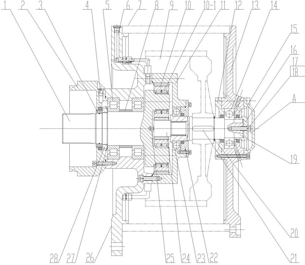
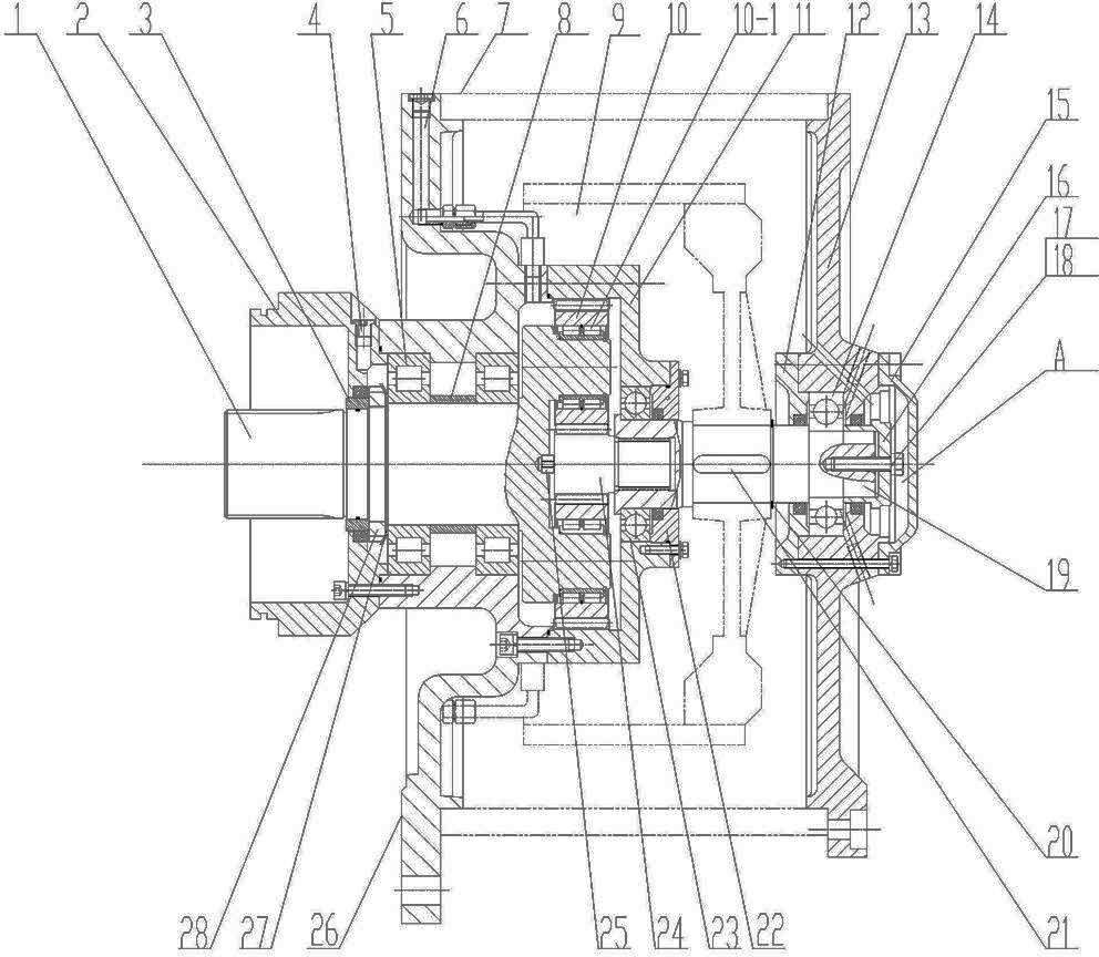
[0015] A mining traction machine with a built-in motor as shown in the accompanying drawing, it includes a motor and a reducer, the motor and the reducer are integrated in the same housing, it includes a cylindrical casing 7, the casing 7 The two ends are respectively fixed with a front end cover 26 and a rear end cover 13. The front end cover 26 is fixed with a reducer housing, and the reducer housing includes a reducer front cover 2 fixed on the outside of the front end cover 26 and a front cover fixed on the front end cover. The ring gear 11 inside 26, the rear end of the ring gear 11 is fixed with a reducer rear cover 22, and a transmission shaft 19 is installed between the reducer housing and the rear end cover 13, and the transmission shaft 19 is keyed to the motor rotor 9. The planetary transmission mechanism is installed in the reducer housing, and the planetary transmission mecha...


PUM


Abstract

The invention, which belongs to the traction machine field, discloses a mining motor built-in traction machine. The traction machine comprises a motor and a speed reducer, wherein the motor and the speed reducer are integrated in a same housing. The traction machine has a cylindrical housing case; a front end cap and a rear end cap are respectively fixed at two sides of the housing case; a speed reducer housing is fixed on the front end cap and comprises a speed reducer front cover and a tooth ring; and a speed reducer rear cover is fixed at a rear end of the tooth ring. A planet speed changemechanism is installed in the speed reducer housing; a transmission shaft is installed between the speed reducer housing and the rear end cap as well as is connected with a motor rotor; the other endof the transmission shaft is installed at the rear end cap by a bearing II; an inner cover and an outer cover are respectively at an inner side and an outboard of the rear end cap; a shaft end cover is fixed at an end of the transmission shaft; and a motor encoder is installed in a space between the shaft end cover, the rear end cap and the outer cover. According to the invention, a speed reducerand a motor are integrated into one and advantages of the two are combined; a volume of the traction machine is substantially reduced; it is convenient for installation; materials and costs are saved; and the traction machine can be used safely and conveniently.

Description

technical field [0001] The invention relates to a traction machine, in particular to a mining traction machine. Background technique [0002] In the existing mine traction machine, its speed reducer and motor are independently arranged. Compared with the motor, the reducer can be easily adjusted steplessly, and the reducer can be made very small under the condition of rated output torque. In the general working conditions of coal mines, although the motor can be used alone and can meet the production requirements, but the volume is very large, not only inconvenient to install, but also the cost is very high, because the motor uses a large number of copper wires and cold-rolled silicon steel sheets, copper wires and silicon steel sheets The price is very high, and the larger the volume, the more materials are needed, and the higher the cost. And setting the reducer and the motor independently will also increase the volume, take up space, and make it inconvenient to use. C...

Claims


Application Information

Patent Timeline
IPC IPC(8): H02K7/116
Inventor 韩永进丁虽要黄春有
Owner XUZHOU KEYUAN HYDRAULIC
Learn More