Magneto-impedance sensor element and method for manufacturing the same

一种传感器元件、磁阻抗的技术,应用在磁阻抗传感器元件,小型化,薄型化领域,能够解决不能充分发挥磁阻抗等问题,达到解除细微加工性、扩大选择范围的效果

Active Publication Date: 2012-01-25
AICHI STEEL
View PDF9 Cites 11 Cited by
  • Summary
  • Abstract
  • Description
  • Claims
  • Application Information

AI Technical Summary

Problems solved by technology

[0014] However, the width of the blade used for grooving of ordinary ceramics is 100 μm or more, and the size of less than 100 μm is a special size, and 50 μm is the minimum grade
[0030] However, compared to MI elements using amorphous wires having circular cross-sections, MI elements using thin-film cores having rectangular film-like cross-sections cannot sufficiently exhibit the effect of magnetoresistance in the width direction of the rectangular film.

Method used


Image

  • Magneto-impedance sensor element and method for manufacturing the same
  • Magneto-impedance sensor element and method for manufacturing the same
  • Magneto-impedance sensor element and method for manufacturing the same

Examples


Embodiment 1

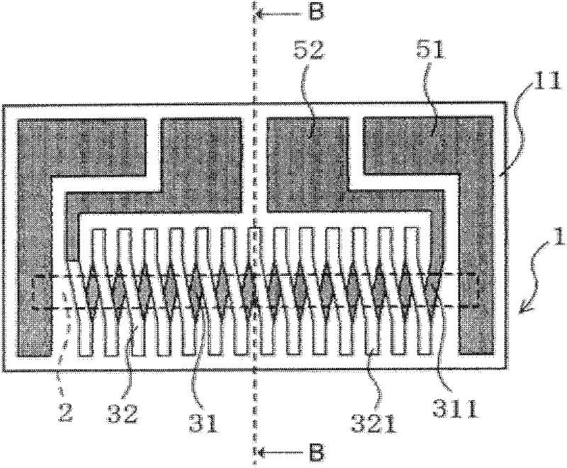
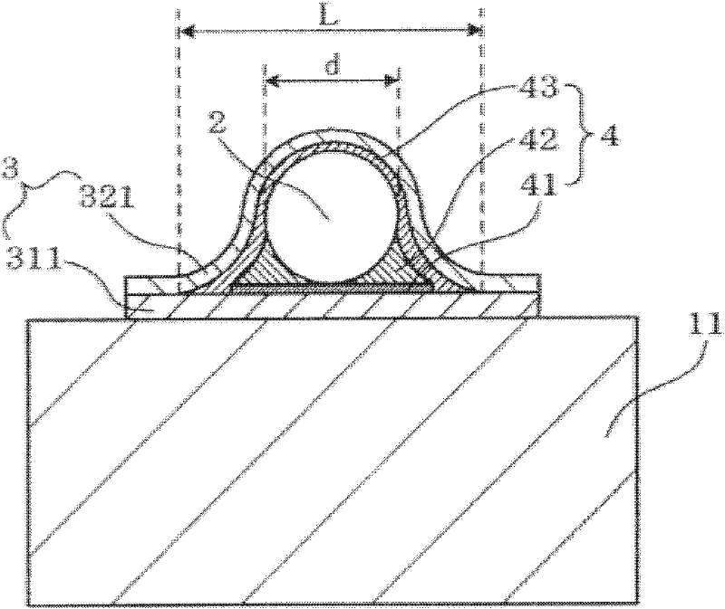
[0127] use figure 1 as well as figure 2 A first embodiment of the planar MI element of the present invention will be described. figure 1 is a conceptual diagram showing the front of the planar MI element 1, figure 2 Yes figure 1 View of the B-B line.

[0128] like figure 1 , figure 2As shown, the magneto-impedance sensor element 1 of the present invention includes a substrate 11 made of a non-magnetic material. In addition, a planar pattern 31 composed of a plurality of first conductor films 311 arranged on a flat surface of the substrate surface is also included. It also includes amorphous wires 2 having a circular cross section arranged along the arrangement direction of the planar patterns 31 across the plurality of first conductor films 311 . Furthermore, an insulator 4 for fixing the amorphous wire 2 to the planar pattern 31 while covering the outer peripheral surface of the amorphous wire 2 is also included.

[0129] In addition, it also includes a three-d...

Embodiment 2

[0174] The material of the amorphous wire in embodiment 2 is the same as that of embodiment 1 and the conventional example, the diameter of the amorphous wire is reduced from 30 μm to 10 μm, and the length is shortened from 0.9 mm to 0.57 mm, and the length of the substrate is also reduced from 1.0mm shortened to 0.6mm. Other conditions are all the same as in Example 1.

[0175] As a result, the circle-equivalent diameter of the detection coil of Example 2 is about 19 μm, which is significantly smaller than that of Example 1, which is about 43 μm, and the height of the substrate as a whole can be further reduced. In addition, the proximity index n=circle-equivalent diameter of the detection coil / diameter of the amorphous wire is n=1.9 in Example 1, which is not as good as in Example 1, but it is closer to winding than n=2.2 in the conventional example.

[0176] Further, L / d=2.8, within the range of 1.3-5.

[0177] Also, the sensitivity of the MI element in Example 2 was 49 m...

Embodiment 3

[0184] This example is a modified example of the configuration of the insulator 4 . like Figure 5 As shown, in this example, the planar insulating portion 41 and the amorphous wire fixing portion 42 are integrally formed at the same time.

[0185] In this case, since the step of forming the planar insulating portion 41 can be omitted, the manufacturing process of the magnetoresistance sensor element 1 becomes simple.


PUM


Abstract

A magneto-impedance sensor element is formed in a planar type structure in which an amorphous wire is incorporated in a substrate. The magneto-impedance sensor element includes a nonmagnetic substrate, an amorphous wire arranged in an aligning direction of a planar pattern that forms a detecting coil, a spiral detecting coil formed of a planar pattern and a cubic pattern on an outer periphery of the amorphous wire, a planar insulating portion that insulates the planar pattern from the amorphous wire, a wire fixing portion to fix the amorphous wire on an upper surface of the planar insulating portion, and a cubic insulating portion that insulates the cubic pattern from the amorphous wire.

Description

technical field [0001] The present invention relates to miniaturization and thinning of a magneto-impedance sensor element (hereinafter referred to as MI element) composed of an amorphous wire used in a magnetic sensor. Background technique [0002] Figure 12 The structure of a conventional MI element is shown (patent document 1). [0003] The MI element 9 is formed by fixing an amorphous wire 92 at the center of a substrate 91 and winding a detection coil 93 around the substrate. In general, the amorphous wire 92 has a length of 4 mm and a diameter of 30 μm, and the size of the MI element is 3 mm in width, 2 mm in height, and 4 mm in length. [0004] The above-mentioned conventional MI element can achieve a certain degree of high sensitivity and miniaturization when used as a magnetic sensor, but the degree of miniaturization is not necessarily sufficient as a high-performance magnetic sensor (hereinafter referred to as MI sensor). [0005] The amorphous wire which is th...

Claims


Application Information

Patent Timeline
Patent Type & Authority Applications(China)
IPC IPC(8): G01R33/02
CPCG01R33/063G01R33/0052G01R33/02
Inventor 本藏义信山本道治西畑克彦
Owner AICHI STEEL
Why Eureka
Try Eureka