Sprue bush and its production method

A technology of runner sleeve and runner, which is applied in manufacturing tools, non-electric welding equipment, welding equipment, etc., can solve the problems of difficulty in manufacturing steel runner sleeve, deterioration of quality of formed products, leakage of cooling water, etc., so as to shorten the forming cycle and form Simple, leak-proof effect

Active Publication Date: 2012-02-01
NGK INSULATORS LTD +1
View PDF5 Cites 5 Cited by
  • Summary
  • Abstract
  • Description
  • Claims
  • Application Information

AI Technical Summary

Problems solved by technology

[0005] However, it is difficult to manufacture strong sprue sleeves such as steel by powder metallurgy
On the other hand, the sprue bushing has a surface that is pushed to the injection port of the injection molding machine to make contact with it. When the sprue bushing formed by powder metallurgy repeatedly contacts the injection port of the injection molding machine, This part is gradually worn out, and the cooling water inside the sprue bushing may leak
In this way, when the cooling water leaked out of the sprue bushing enters the runner and the cavity, the quality of the molded product will deteriorate.

Method used


Image

  • Sprue bush and its production method
  • Sprue bush and its production method
  • Sprue bush and its production method

Examples


Embodiment Construction

[0020] Embodiments of the present invention will be described below.

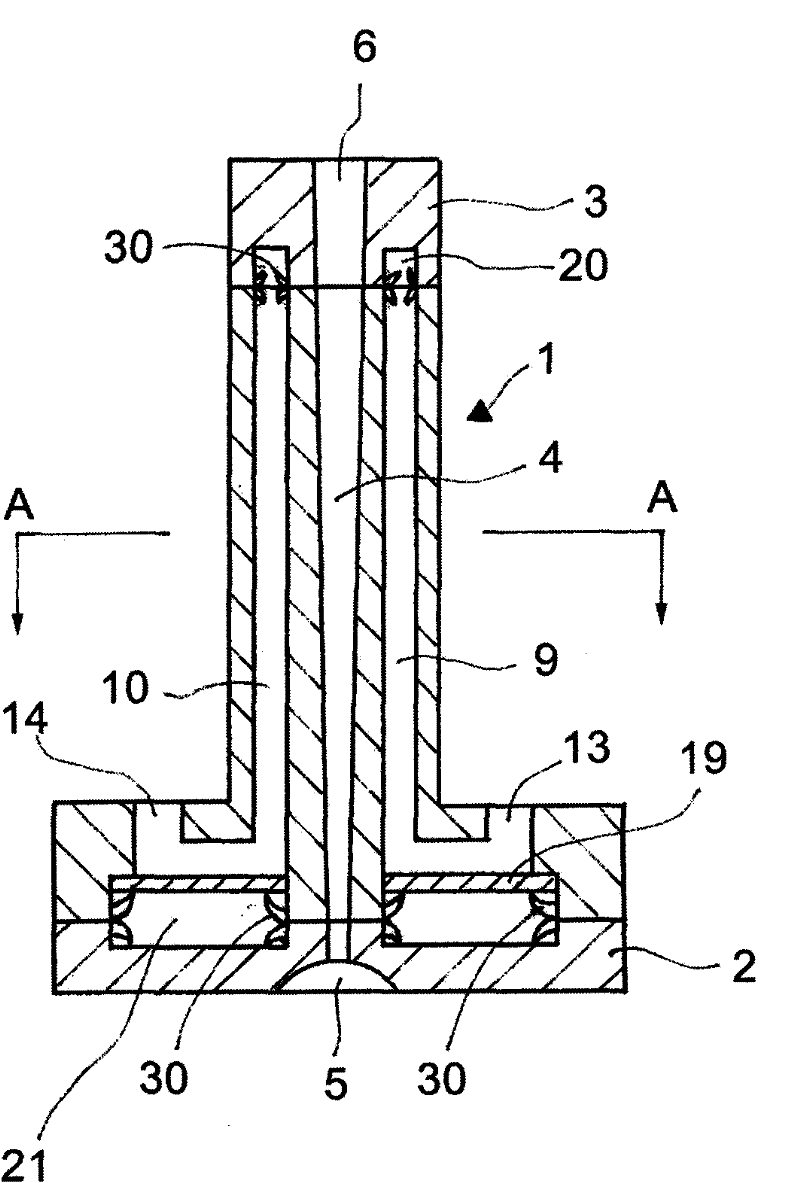
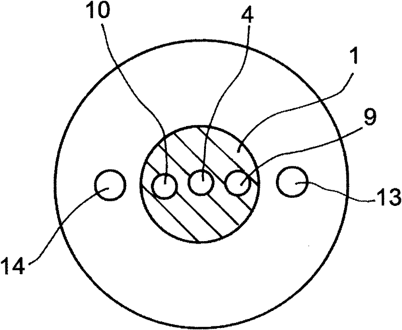
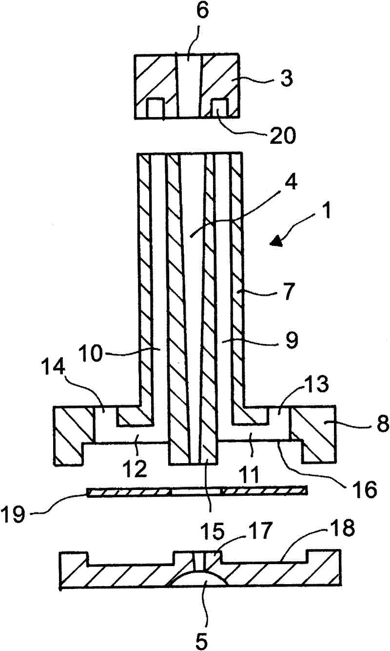
[0021] figure 1 It is a cross-sectional view showing an embodiment of the sprue bushing of the present invention, figure 2 is its cross-sectional view, image 3 is its component diagram, Figure 4 It is an explanatory diagram of the state of use. In the embodiments described below, each component is made of a metal material having high strength such as stainless steel, steel, and copper alloy.

[0022] First, use figure 1 The structure of the sprue bushing according to the embodiment will be described. Reference numeral 1 is the main body of the sprue bushing, and 2 is a flange plate integrally formed by friction pressure welding on the back side thereof. In addition, in this embodiment, the nozzle part 3 is integrally joined to the front-end|tip of the sprue bushing main body 1 similarly by friction pressure welding. Reference numeral 4 is a sprue formed at their center, the end of the back side of ...


PUM


Abstract

The invention provides a sprue bush advantaged by shortening of forming period via effectively cooling a molten resin filled in a sprue and excellent durability. The sprue bush is characterized by comprising: a sprue bush main body (1) cooling water channels (9, 10) at the periphery of a sprue (4) at the center; and a protruding flange plate (2) disposed at the back surface side of the sprue bush main body (1), the components are welded to be an integration via friction press force. The sprue bush can be made from hard metal materials and no danger of water leakage is provided.

Description

technical field [0001] The present invention relates to a sprue bush for injecting molten resin into a cavity of an injection mold and a method for manufacturing the same. Background technique [0002] Conventionally, an injection molding method in which a resin melted by heating is injected into a cavity of a mold and solidified to form a product has been widely used. The injection mold has a cavity portion for molding a product, a sprue bushing for injecting molten resin into the cavity portion, and a runner connecting an injection port at the front end of the sprue bushing and the cavity portion. Such an injection mold is opened after the molten resin filled in the cavity is sufficiently solidified, and a molded product is taken out therefrom. [0003] Generally, both the runner and the runner are larger than the cavity part in terms of volume per unit area. Therefore, the time required for the molten resin to solidify is longer in the runner and the runner as the runne...

Claims


Application Information

Patent Timeline
Patent Type & Authority Applications(China)
IPC IPC(8): B29C45/27B23K20/12
CPCB29C45/2701B29C45/2737
Inventor 杉浦尚泽延宏
Owner NGK INSULATORS LTD
Why Eureka
Try Eureka