Lifting appliance special for beam of large press

A technology for presses and beams, applied in the field of presses, can solve problems such as hidden dangers of lifting and damage to steel wire ropes, and achieve the effects of avoiding hidden dangers, reducing occupied area, and having a simple and reasonable structure.

Active Publication Date: 2012-02-01
RONGCHENG METAL FORMING MACHINE GROUP
View PDF5 Cites 2 Cited by
  • Summary
  • Abstract
  • Description
  • Claims
  • Application Information

AI Technical Summary

Problems solved by technology

Since the height of the lifting lug must be lower than the top plane of the beam body during processing, when the steel wire rope fixed on the lifting lug is used for hoisting, the steel wire rope will be rubbed by the edges and corners on both sides of the beam body, forming a destructive force on the steel wire rope, causing the wire rope The damage will bring hidden danger to the lifting safety

Method used


Image

  • Lifting appliance special for beam of large press
  • Lifting appliance special for beam of large press
  • Lifting appliance special for beam of large press

Examples


Embodiment Construction

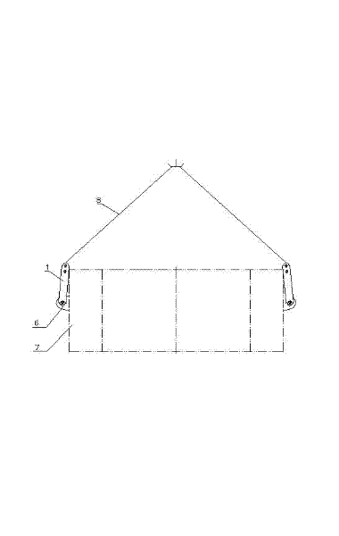
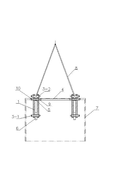
[0012] Such as figure 1 , figure 2 As shown, a special spreader for large press beams, the spreader includes 4 sets of the same lifting lug clamps, each set of 2 sets of lifting lug clamps are set on the 2 lifting lugs on one side of the beam 7 as a group, and the wire rope 8 passes through The connecting lugs form a four-point pull to the crossbeam 7, so as to realize the smooth lifting of the crossbeam 7.

[0013] Such as figure 2 As shown, each set of lug clips includes two identical pull plates 1 .

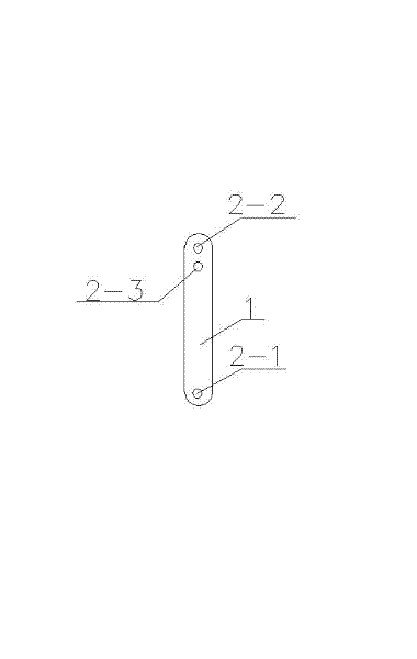
[0014] Such as image 3 As shown, the lower part of the surface of each pull plate 1 is provided with a lifting eye hinge hole 2-1, and the upper part of the surface of the pull plate is provided with a load-bearing bolt hole 2-2.

[0015] Such as figure 1 , figure 2 As shown, when the pull plate 1 is produced, the distance between the hinged hole 2-1 of the lifting lug and the load-bearing bolt hole 2-2 must be greater than the distance between the lifting lug 6 of t...


PUM


Abstract

The invention belongs to the technical field of presses. In order to overcome the defect that a beam applies destructive force to a steel wire rope in the conventional lifting process, the invention provides a lifting appliance special for a beam of a large press according to the technical scheme. The lifting appliance is provided with a combined lifting lug clip, wherein the lifting lug clip comprises two identical pull plates; a lifting lug hinged hole is formed on the lower part of the surface of each pull plate; a load-bearing bolt hole is formed on the upper part of the surface of each pull plate; a distance between the lifting lug hinged hole and the load-bearing bolt hole is greater than a distance between a lifting lug of the beam and the upper surface of the beam; the two pull plates are laterally arranged on two sides of the lifting lug to clamp the lifting lug; a hinged bolt passes through the lifting lug hinged holes on the two pull plates and a through hole on the liftinglug, so that the two pull plates are hinged with the lifting lug; and a load-bearing bolt passes through the load-bearing bolt holes on the two pull plates, so that the upper ends of the two pull plates are connected. The lifting appliance has a simple and reasonable structure and is high in adaptability.

Description

[0001] technical field [0002] The invention belongs to the technical field of presses, and in particular refers to a special spreader for a beam of a large press. Background technique [0003] The hoisting of the beam of the large press needs to be hoisted by an industrial horizontal truck crane. When the beam is processed, two lifting lugs of equal height are set on each side of the beam body. The wire rope connects the lifting lugs to form a four-point pull to achieve stable lifting. transport. Since the height of the lifting lug must be lower than the top plane of the beam body during processing, when the steel wire rope fixed on the lifting lug is used for hoisting, the steel wire rope will be rubbed by the edges and corners on both sides of the beam body, forming a destructive force on the steel wire rope, causing the wire rope The damage will bring hidden danger to the lifting safety. Contents of the invention [0004] The purpose of the present invention is to p...

Claims


Application Information

Patent Timeline
Patent Type & Authority Applications(China)
IPC IPC(8): B66C1/12
Inventor 于岩
Owner RONGCHENG METAL FORMING MACHINE GROUP
Why Eureka
Try Eureka