
Strap for securing exhaust treatment device

An exhaust treatment device and technology for exhaust treatment, which are used in exhaust devices, mufflers, applications, etc.

Inactive Publication Date: 2012-02-01
CATERPILLAR INC
View PDF7 Cites 14 Cited by
  • Summary
  • Abstract
  • Description
  • Claims
  • Application Information

AI Technical Summary

Problems solved by technology

For example, '090 devices may have high stress concentrations at the eyelets, thus potentially causing premature failure of the device

Method used


Image

  • Strap for securing exhaust treatment device
  • Strap for securing exhaust treatment device
  • Strap for securing exhaust treatment device

Examples


Embodiment Construction

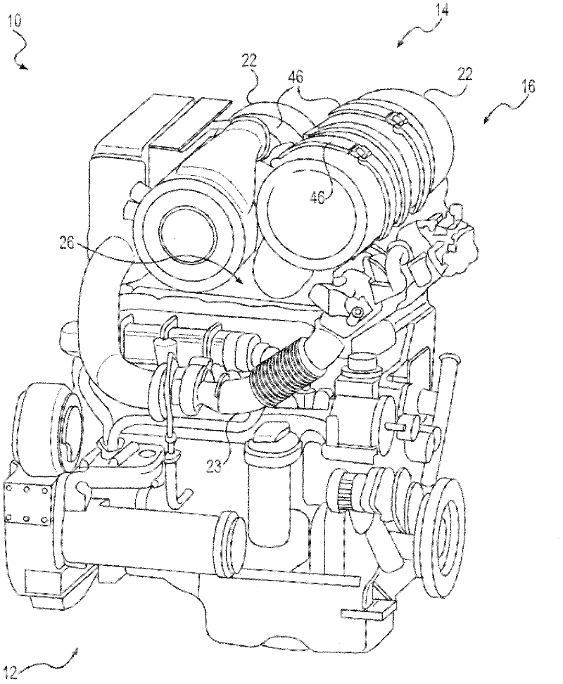
[0018] figure 1 A schematic diagram of a power system 10 is shown, which may include a power source 12 and an exhaust system 14 . For example, power source 12 may embody a combustion engine such as a diesel engine, a gasoline engine, a gaseous fuel powered engine (eg, a natural gas engine), or any other type of combustion engine known to those skilled in the art.

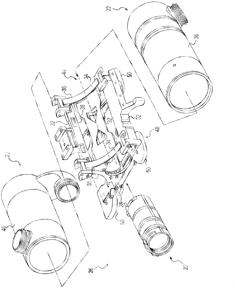
[0019] Exhaust system 14 may direct exhaust gas from power source 12 to emission control system 16 via exhaust pipe 23 . After passing through emission control system 16 , the exhaust gas may be directed to the atmosphere. Emission control system 16 of exhaust system 14 may be configured to monitor, control, and / or modify exhaust emissions. Emission control system 16 may include one or more exhaust treatment devices 22 and bracket 26 .

[0020] Exhaust treatment device 22 may be configured to reduce emissions of noxious gases, particulate matter, and / or noise from power source 12 . Each exhaust treatment device ...


PUM


Abstract

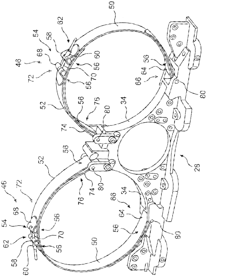
A strap for securing an exhaust treatment device is disclosed. The strap has a first strap member that includes a coupler on a first end and a loop on a second end. The strap has a second strap member that is provided with the coupler on the first end. The coupler is configured to link with the coupler of the first strap member. The second strap member is provided with the loop on the second end. The loop includes a flexible material strap which forms the loop and is fixed on a point of securement. A loop length is not smaller than one third of the effective length of the strap. The effective length is defined as a distance from an end of the loop of the first strap member to an end of the loop of the second strap member when the coupler of the first strap member is coupled to the coupler of the second strap member. The loop length is defined as a distance from an end of the loop of the second strap member to the point of securement.

Description

technical field [0001] The present invention relates generally to straps and, more particularly, to straps for securing exhaust treatment devices in emission control systems. Background technique [0002] In order to comply with emission standards, the machinery manufacturing industry has developed and implemented a variety of exhaust treatment devices to reduce pollutants in the exhaust before it is released into the atmosphere. Exhaust treatment devices may include, for example, diesel particulate filters, selective catalytic reduction devices, diesel oxidation catalysts, fuel fired burners for regenerating the diesel particulate filters, mufflers, and other similar components. [0003] Due to the increasing complexity and number of exhaust treatment devices, and the small amount of space available, manufacturers mount several exhaust treatment devices together on a single structure or bracket. However, securing some exhaust treatment devices in the brackets in a reliable...

Claims


Application Information

Patent Timeline
Patent Type & Authority Applications(China)
IPC IPC(8): F01N13/18
CPCF01N13/1805Y10T24/14
Inventor S·哈桑F·M·I·坎谈东明T·V·斯塔利R·A·克兰德尔P·F·奥尔森R·L·马奎斯C·A·科尔曼朱健希
Owner CATERPILLAR INC
Learn More