

Refrigerating and compressing expansion machine
A refrigeration compression and expander technology, applied in the field of refrigeration, can solve the problems of large throttling loss and difficulty in achieving refrigeration efficiency.
Inactive Publication Date: 2012-02-01
蔡学功
View PDF0 Cites 5 Cited by
- Summary
- Abstract
- Description
- Claims
- Application Information
AI Technical Summary
Problems solved by technology
Moreover, due to the large throttling loss, it is difficult for the traditional carbon dioxide refrigeration system to achieve high refrigeration efficiency.
Method used
View moreImage
Smart ImageViewing Examples

Examples
Embodiment Construction
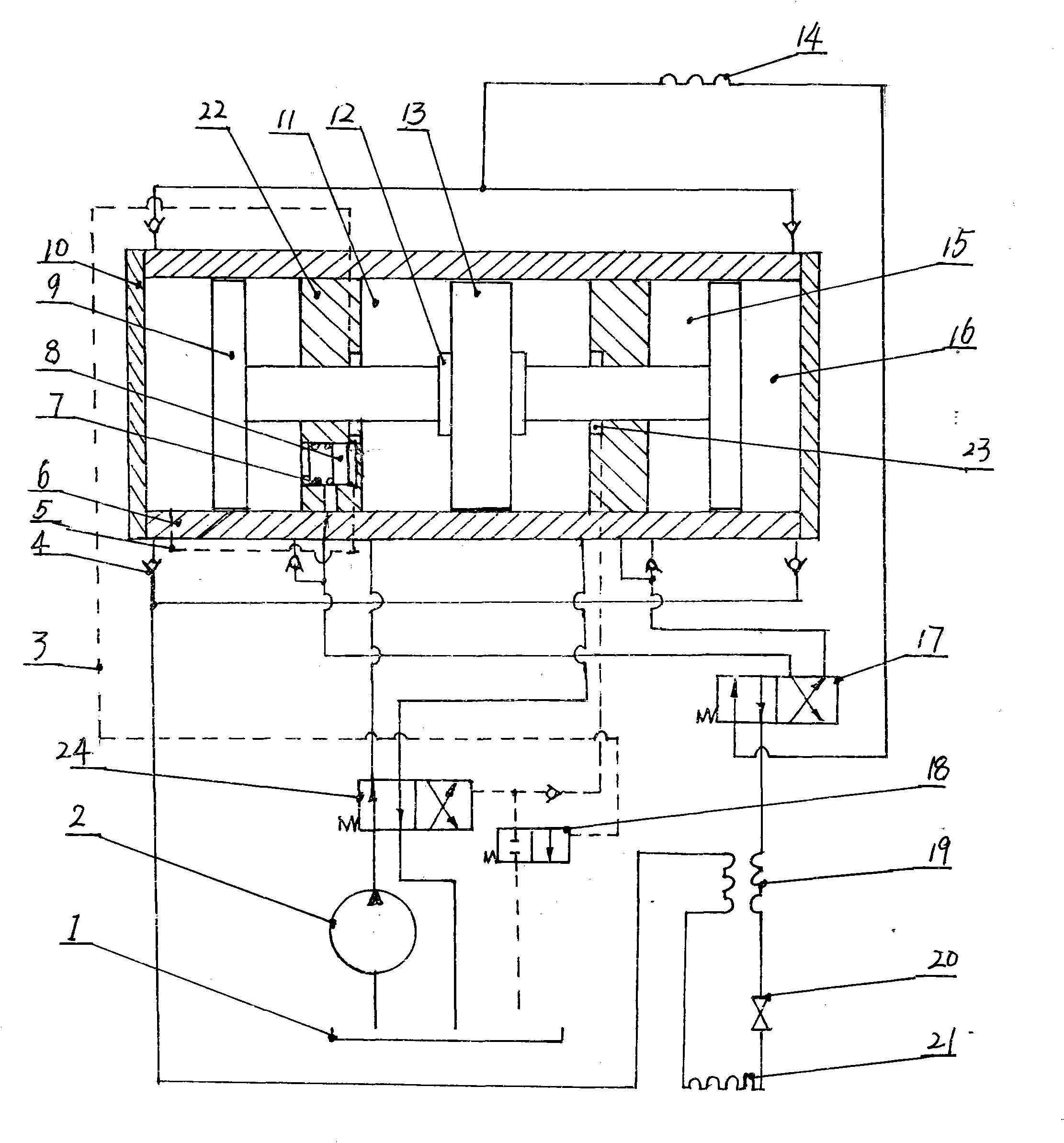
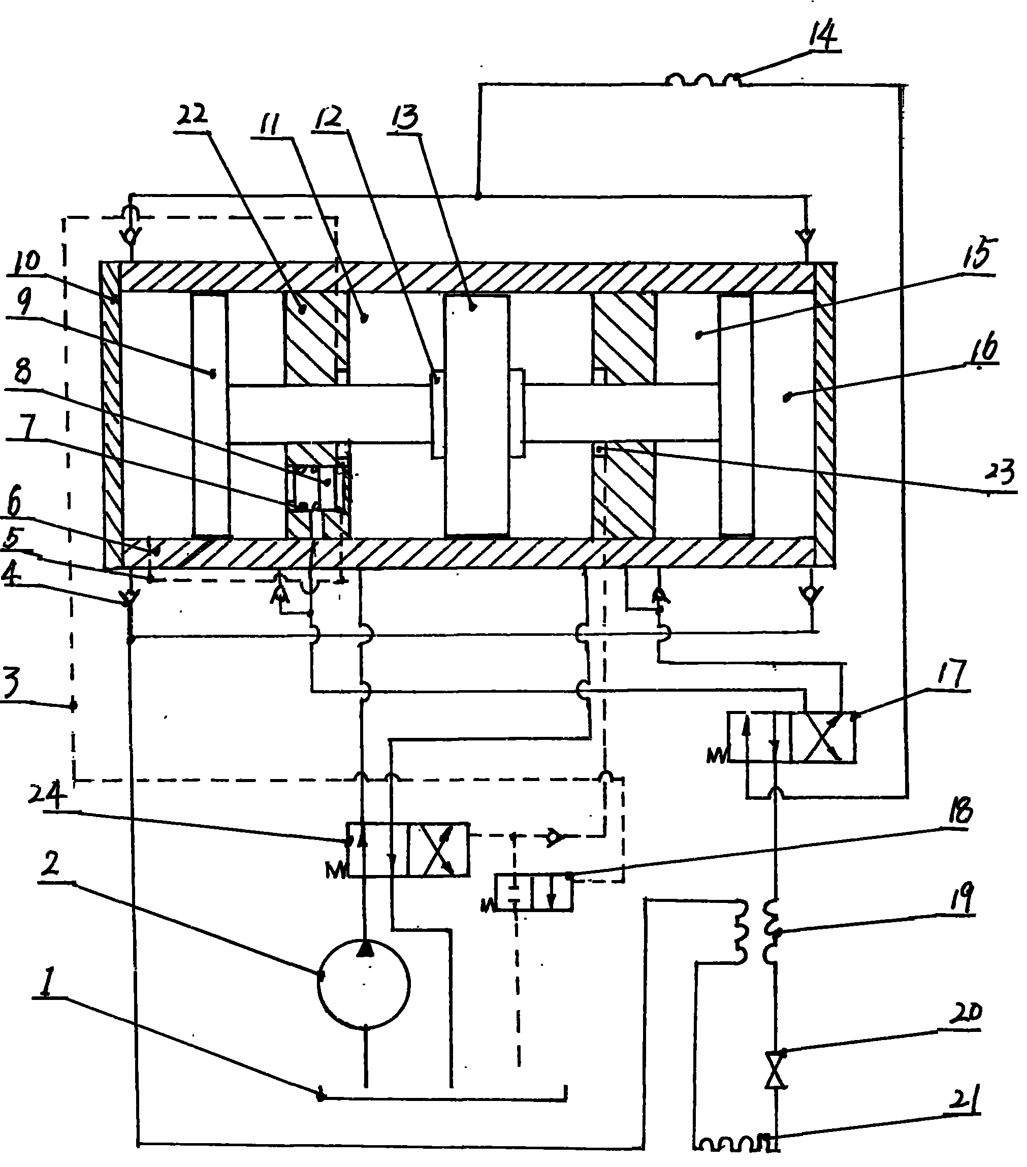
[0007] The oil pump (2) reversing valve (24), gas-liquid energy conversion cylinder (6), cooler (14), gas path reversing control valve (17), and regenerator in the refrigeration compression expander in the accompanying drawings (19), throttling valve (20) evaporator (21) are connected successively with pipeline, and the working medium in the system is carbon dioxide.
Login to View More PUM
 Abstract
The invention relates to a refrigerating and compressing expansion machine which comprises an oil pump, a gas-liquid energy conversion cylinder, a gas circuit reversing control valve, a reversing valve and the like. The working principle of the machine provided by the invention is as follows: when the oil pump begins operating, the gas circuit reversing control valve and the reversing valve enable hydraulic oil generated by the oil pump to enter a left hydraulic oil cylinder and a right hydraulic oil cylinder of the gas-liquid energy conversion cylinder alternatively, introduce the cooled high-pressure gas into an expansion cavity for expansion to do work, and jointly push a piston to move left and right to compress the gas in a compression cavity; the gas is discharged into a cooling device; heat is discharged and temperature is lowered in the cooling device, the gas enters an evaporator after being subjected to further temperature reduction and depressurization performed by a heat regenerator and a throttling valve, and the gas is subjected to heat absorption, evaporation and refrigeration; and the generated steam is absorbed into the gas-liquid energy conversion cylinder again. Because hydraulic oil is generated by the hydraulic pump, higher compression pressure can be obtained easily, and the compression of carbon dioxide is realized through a gas-liquid energy converter; and the gas leakage is less, and the gas transmission efficiency is high.
Description
technical field [0001] The invention belongs to the technical field of refrigeration. Background technique [0002] Nowadays, human beings pay more and more attention to the protection of the ozone layer and climate warming, which makes carbon dioxide, an environmentally friendly refrigerant, attract people's attention again; but this refrigeration system also has deficiencies, and the carbon dioxide gas must Only under pressure can it be fully cooled. For this, a compressor capable of withstanding high pressure is required. Moreover, due to the large throttling loss, it is difficult for the traditional carbon dioxide refrigeration system to achieve high refrigeration efficiency. Contents of the invention [0003] The object of the present invention is to provide a refrigeration compressor expander, which uses a hydraulic pump to generate power, and realizes the compression of carbon dioxide gas by hydraulic pressure; it can easily obtain high compression pressure, and h...
Claims
Login to View More Application Information
Patent Timeline
 IPC IPC(8): F04B35/02
Inventor 蔡学功
Owner 蔡学功