
Sensor device for detecting environmental conditions

A sensor device and a technology for detecting the environment are applied to devices with multiple detectors, measuring devices, photometry using electric radiation detectors, etc., which can solve the problem of high cost and achieve the effect of compact appearance

Active Publication Date: 2016-04-20
HELLA KG HUECK & CO
View PDF7 Cites 0 Cited by
  • Summary
  • Abstract
  • Description
  • Claims
  • Application Information

AI Technical Summary

Problems solved by technology

The resulting costs are particularly high when installing multiple sensors or sensor systems, since a large number of diodes and mirrors have to be installed

Method used


Image

  • Sensor device for detecting environmental conditions
  • Sensor device for detecting environmental conditions
  • Sensor device for detecting environmental conditions

Examples


Embodiment Construction

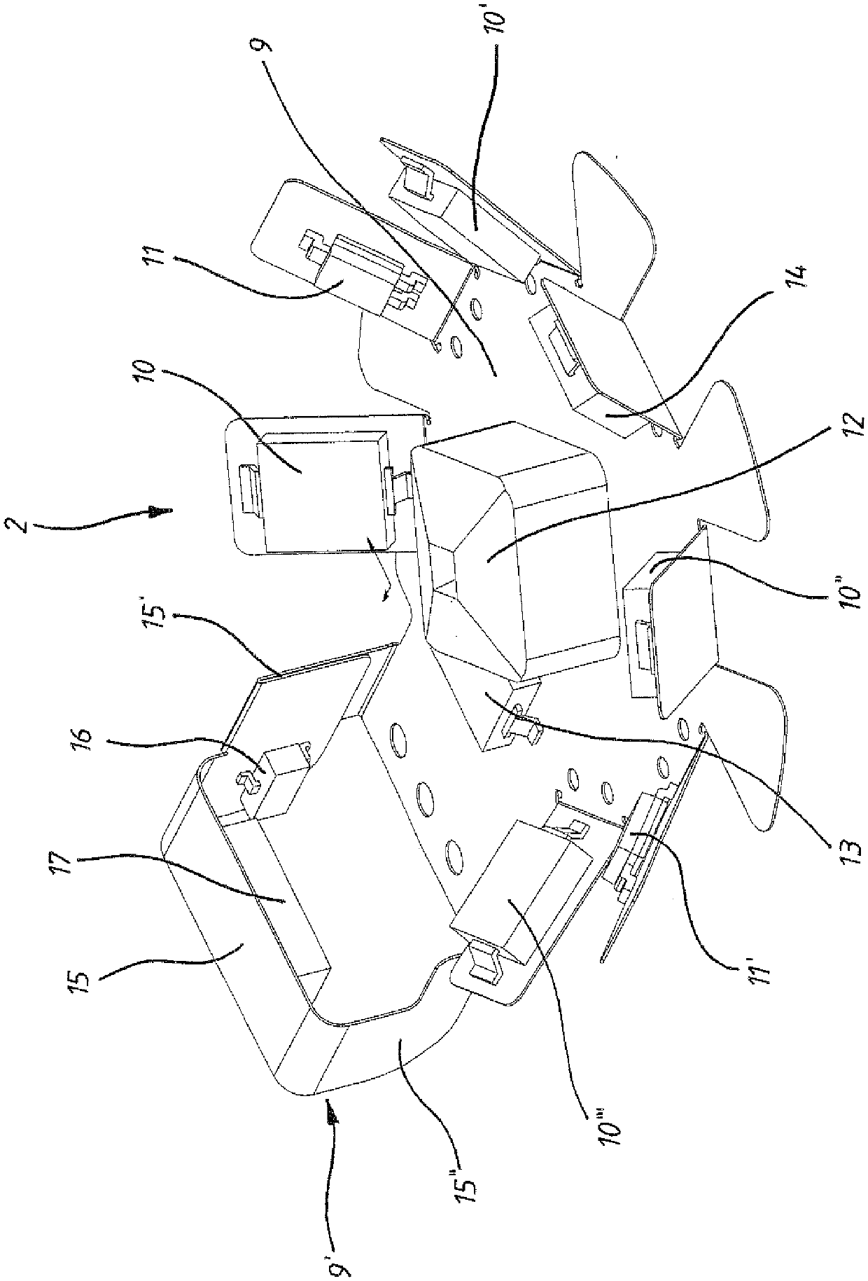
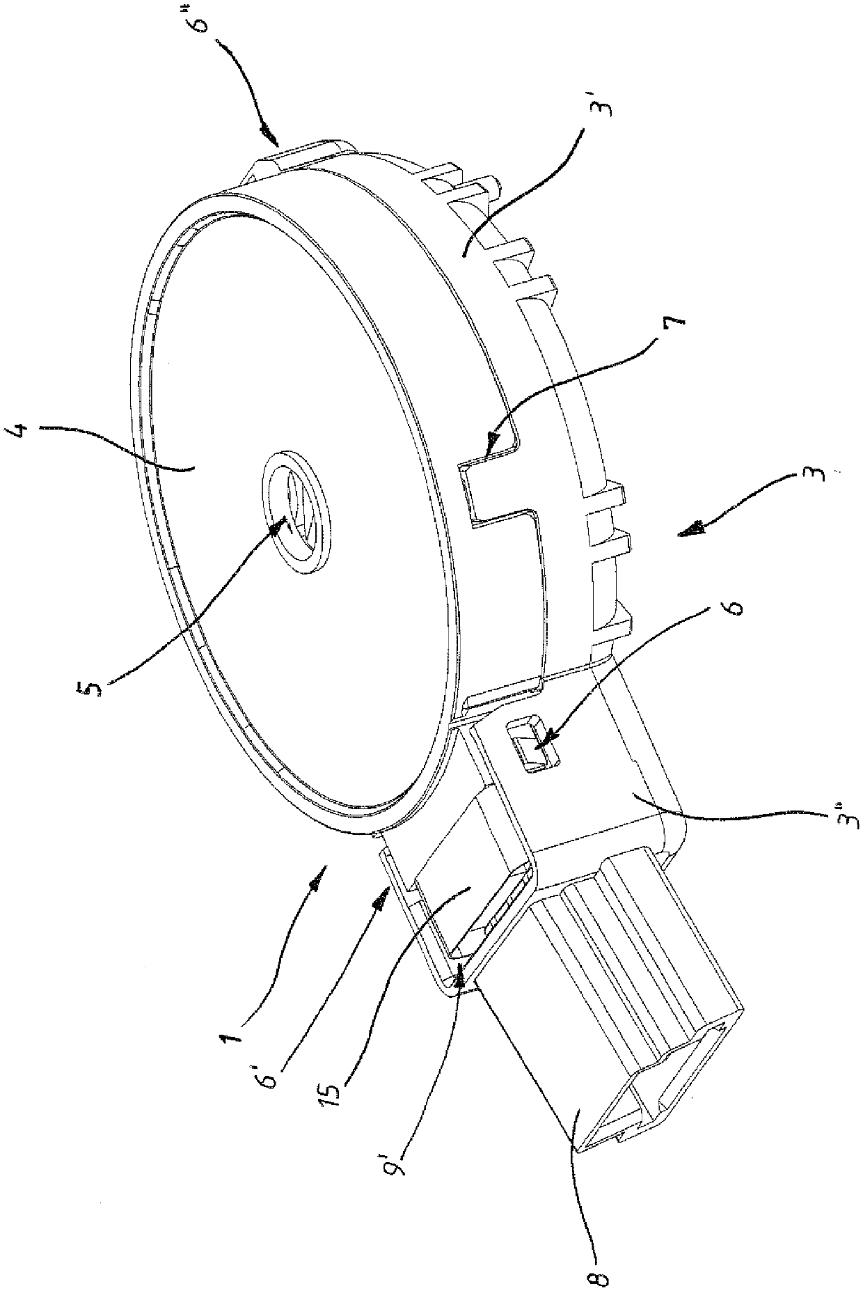
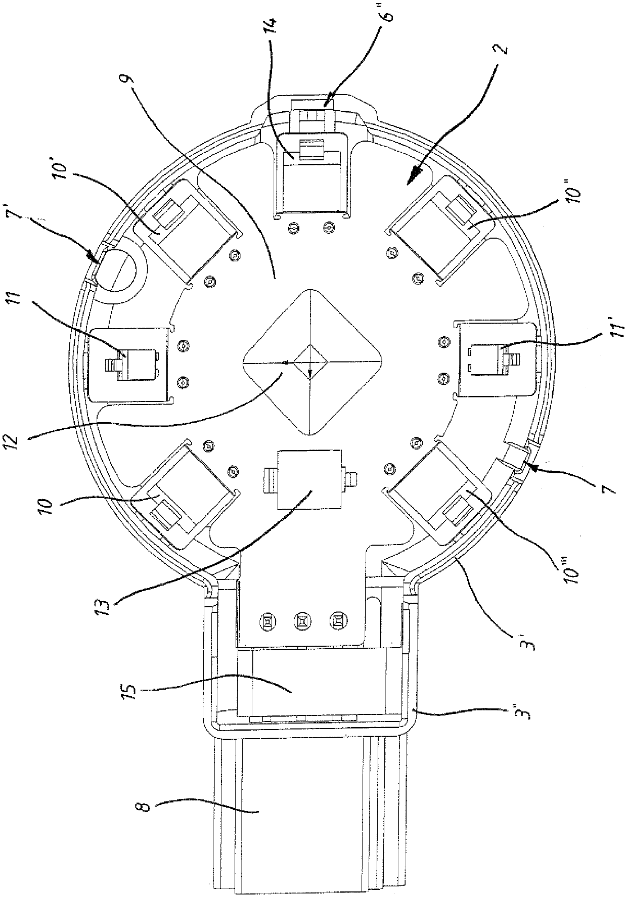
[0022] The housing of the sensor device 2 is denoted by 1 ( figure 2). This housing 1 has a receptacle 3 and a cover 4 which are releasably connected to one another. The cover plate 4 is substantially circular and has a perforation 5 in the central region of the formed circle. The receiving part 3 has a circular first receiving area 3' and an elongated second connecting area 3". To connect the receiving part 3 and the cover plate 4, three stop connections 6, 6' are provided , 6" and two plug connectors 7, 7'. The receiving part 3 has three stop elements of the stop connection 6 , 6 ′, 6 ″, of which two stop elements of the stop connection 6 , 6 ′ Arranged on the elongated connection region 3 ″ at the first end of the connection region 3 ″ which rests on the receiving region 3 ′, and the third locking element of the locking connection 6 ″ is located at the The circular receiving area 3' is arranged on the side opposite to the elongated connecting area 3". In addition, the ...


PUM


Abstract

The invention relates to a sensor device for detecting ambient conditions, in particular for a motor vehicle, which sensor device has at least one carrier board, in particular a printed circuit board, and optical elements arranged on the carrier board, wherein a plurality of optical elements surround a A common central area is arranged on the carrier plate, and at least two of the optical elements arranged around the central area have a main axis of action. These main action axes are positioned at a predetermined angle relative to the carrier plate, wherein the main action axes point towards the common central area. Further sensors arranged on the carrier plate are, for example, rain sensors, sunlight sensors and different light sensors which are preferably arranged on the receiving surface of the carrier plate.

Description

technical field [0001] The invention relates to a sensor device, in particular for a motor vehicle, for detecting ambient conditions, the sensor device having at least one carrier board, in particular a printed circuit board, and optical elements arranged on the carrier board. Background technique [0002] Optical elements arranged on a carrier plate for detecting ambient conditions are known from various applications. An example for using a sensor device in a motor vehicle is the control of the lights of the motor vehicle as a function of the driving situation of the motor vehicle as disclosed in DE 19630216 A1. Further sensor devices record data enabling climate control in the passenger compartment of the motor vehicle or detect precipitation in order to automatically activate windshield wipers of the motor vehicle, for example. A disadvantage of existing systems is that they are designed discretely, that is to say at least one sensor or a sensor device with one or more o...

Claims


Application Information

Patent Timeline
Patent Type & Authority Patents(China)
IPC IPC(8): G01J1/06G01W1/14
CPCB60S1/087B60S1/0888G01J1/02G01J1/0271G01J1/4228G01K2205/00G01W1/02G01N21/00B60R21/00
Inventor T.尼曼O.吕特克A.施拉尔曼J.帕洛克斯A.米勒T.佩塔施
Owner HELLA KG HUECK & CO
Learn More