Melt spinning equipment

A melt-spinning and equipment technology, which is applied in the field of melt-spinning equipment and can solve problems such as the sensitivity of optical sensors

Active Publication Date: 2022-03-22
OERLIKON TEXTILE GMBH & CO KG
View PDF4 Cites 0 Cited by
  • Summary
  • Abstract
  • Description
  • Claims
  • Application Information

AI Technical Summary

Problems solved by technology

Guaranteeing the sensitivity of this optical sensor over a relatively long operating period is a serious problem in view of the melt-spinning plant environment which is heavily burdened by volatile components

Method used


Image

  • Melt spinning equipment
  • Melt spinning equipment
  • Melt spinning equipment

Examples


Embodiment Construction

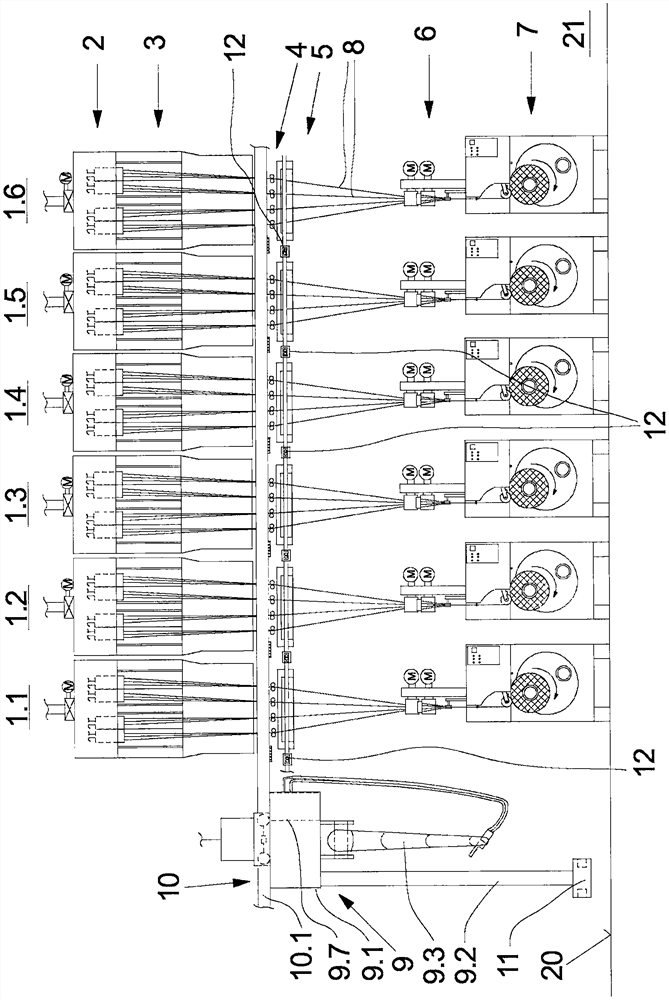
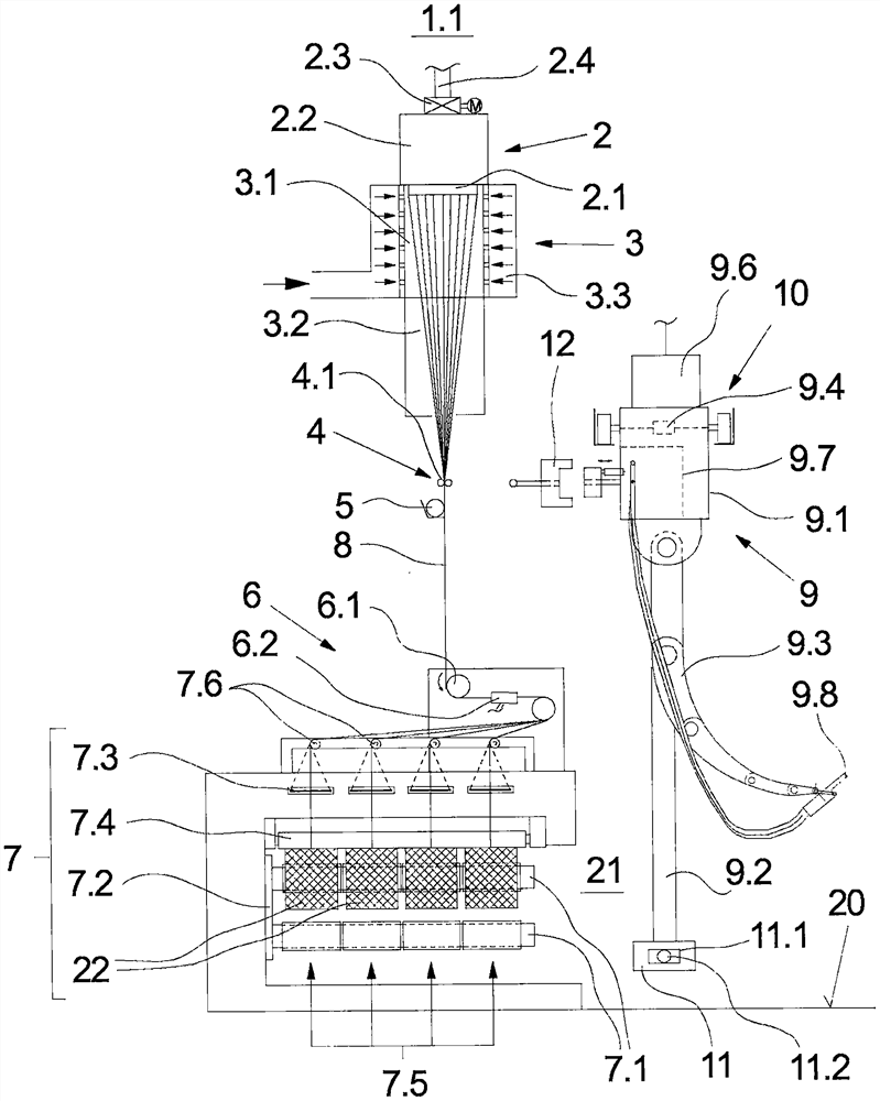
[0027] exist figure 1 and image 3 The middle front and side views show an embodiment of the melt spinning apparatus of the present invention with multiple spinning positions. The following description applies to both figures unless one of them is explicitly mentioned.

[0028] An embodiment of the melt-spinning apparatus according to the invention has a plurality of spinning positions 1.1-1.6 which are aligned with each other and form the machine longitudinal side. figure 1 The number of spinning positions described is only exemplary. In principle, such a melt-spinning plant contains several spinning positions of the same type.

[0029] like figure 1 and image 3 The spinning positions 1.1-1.6 shown are realized in the same manner in terms of their structure. The following will be used as image 3 An example of the spinning position 1.1 shown in the side view is used to describe the device in more detail.

[0030] Each spinning position 1.1-1.6 has a spinning nozzle a...


PUM


Abstract

The invention relates to a melt-spinning plant for the production of synthetic yarns, having a plurality of spinning positions. Each spinning position has a spinning nozzle arrangement, a cooling arrangement, a godet arrangement and a winding arrangement. An automatic operating mechanism is provided for inserting the yarn into the spinning positions, said operating mechanism being movable to each spinning position in order to insert the yarn. The automatic operating mechanism is guided via a guide above the operator corridor and has at least one collision sensor for detecting obstacles. In order to be able to carry out all operating processes with high safety in one spinning position, the robot has a sensor column for accommodating the crash sensor and protrudes into the operator corridor at a distance from the plant floor .

Description

technical field [0001] The present invention relates to a melt spinning apparatus for producing synthetic yarns. Background technique [0002] The production of synthetic yarns is carried out by means of melt-spinning plants with several spinning positions. Here, the spinning positions are arranged next to each other to form the machine longitudinal front in the plant building. Each spinning position has a spinning nozzle arrangement with a plurality of spinning nozzles for extruding a plurality of yarns. The yarns at the spinning position are withdrawn collectively as a yarn group from the spinning nozzle and at the end of the process are wound in parallel on several winding stations of the winding device to form bobbins. The winding devices at the spinning position are each equipped with two winding spindles held on the winding turntable, enabling continuous production of yarn at the spinning position. Only at the start of the process or in the event of an interruption ...

Claims


Application Information

Patent Timeline
Patent Type & Authority Patents(China)
IPC IPC(8): D01D7/00D01D13/00D01D13/02B65H54/24B65H54/26D01H13/00D01H13/14
CPCB65H54/26D01H13/005D01D7/00D01D13/00D01D13/02B65H54/88B65H57/003B65H2701/3132
Inventor R·沃斯S·福尔斯蒂奇M-A·赫尔恩多夫A·哈米德
Owner OERLIKON TEXTILE GMBH & CO KG
Why Eureka
Try Eureka