Apparatus for producing plastic parts interspersed with reinforcing fibres

A technology of plastic parts, reinforcing fibers, used in mixers, fluid mixers, transportation and packaging, etc., can solve problems such as unusable clean pistons

Inactive Publication Date: 2012-02-01
KRAUSSMAFFEI TECH GMBH
View PDF6 Cites 4 Cited by
  • Summary
  • Abstract
  • Description
  • Claims
  • Application Information

AI Technical Summary

Problems solved by technology

However, this device cannot be used with a reciprocating cleaning piston

Method used


Image

  • Apparatus for producing plastic parts interspersed with reinforcing fibres
  • Apparatus for producing plastic parts interspersed with reinforcing fibres
  • Apparatus for producing plastic parts interspersed with reinforcing fibres

Examples


Embodiment Construction

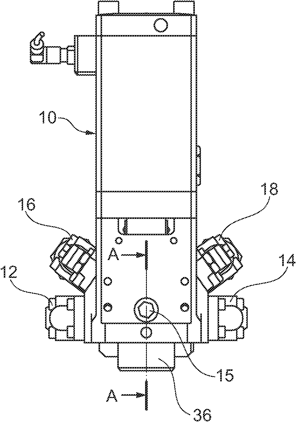
[0022] exist figure 1 A schematic front view of a mixing head 10 with a corresponding housing and two material supply lines 12 and 14 and two material recirculation lines 16 and 18 is shown in . At the lower end of the mixing head 10 can be seen an outlet duct 36 from which the mixture of fibers and reaction components exits, as will be described below.

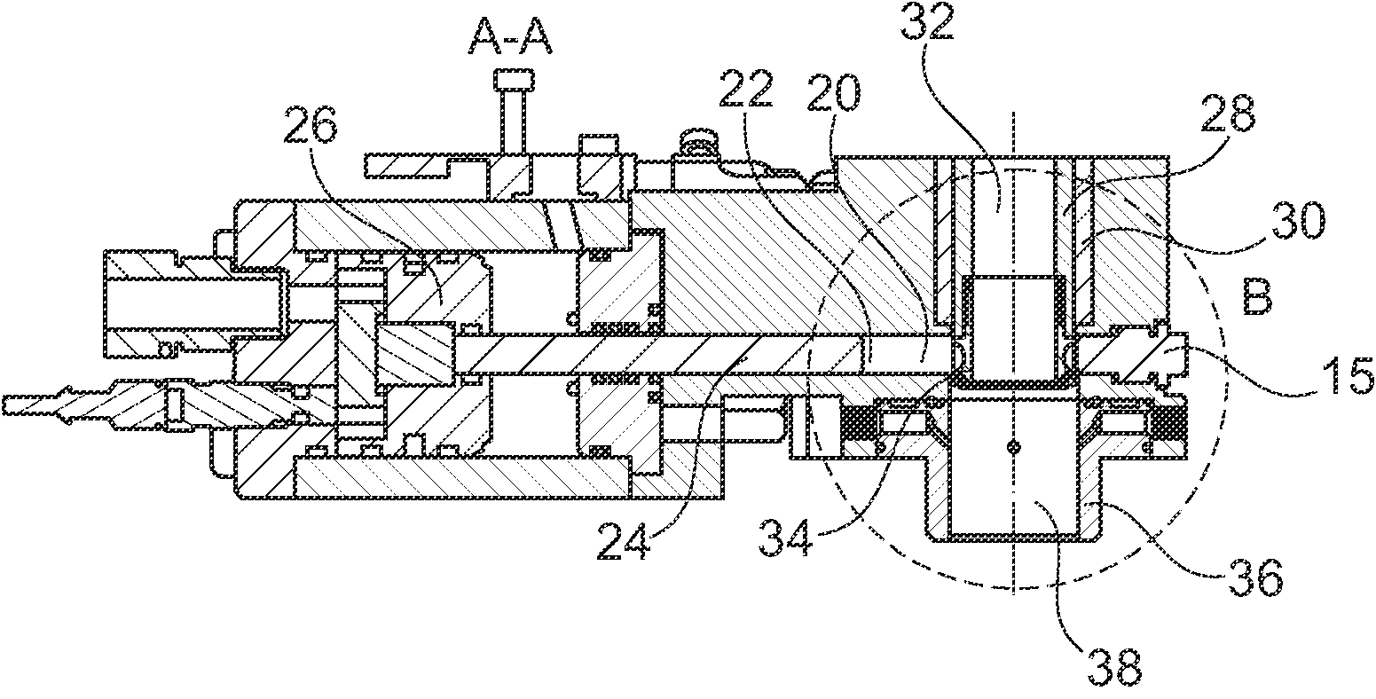
[0023] exist figure 2 shown in figure 1 A sectional view of the lower portion of the mixing head shown along the line A-A. In this case, the mixing head 10 has, in a bore of its housing, a bushing 30 in which the cleaning piston 28 is guided so as to be movable back and forth. Both the bushing 30 and the cleaning piston are only partially shown here (the respective lower region). A fiber feed channel 32 of circular cross-section is formed in the interior of the cleaning piston 28 and extends coaxially to the housing bore.

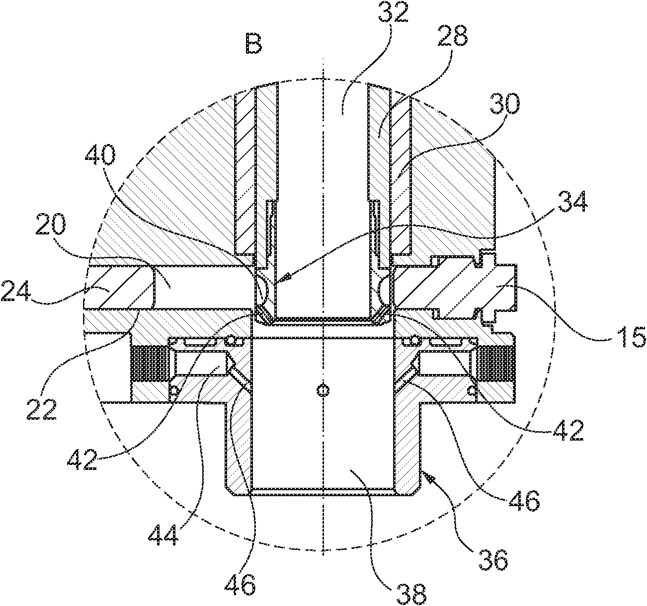
[0024] The fiber feed channel 32 of the cleaning piston 28 opens into a coaxial cylindrical outle...


PUM


Abstract

The present invention relates to an apparatus for producing plastic parts interspersed with reinforcing fibres, with a mixing chamber (20) for producing a mixture of chemically reactive polymer components, with an outlet chamber (38), which is arranged downstream of the mixing chamber and in which a cleaning ram (28) in which a fibre conveying channel (32) is formed is guided in a reciprocatingly movable manner. The invention is characterized in that the end face of the cleaning ram is provided with a die (34), through which the fibre conveying channel (32) extends and arranged on the outer circumference of which there is an annular groove (40), which is at a distance from the end of the die (34) and can be positioned in such a way that, in a first working position, a flow connection between the mixing chamber (20) and the annular groove (40) is formed and, in another working position of the cleaning ram (28), the flow connection between the mixing chamber (20) and the annular groove (40) is interrupted and in that at least one die channel (42), preferably a plurality of die channels (42), is / are formed between the annular groove (40) and the outlet-side end of the die (34), said channel(s) opening at the end face into the outlet chamber (38).

Description

technical field [0001] The invention relates to a plant for producing plastic parts incorporating reinforcing fibers according to the preamble of claim 1 . Background technique [0002] Such devices are known from the prior art. EP 771 259 B1 discloses a similar device for producing plastic parts incorporating reinforcing fibers, in which device a cleaning piston is guided reciprocally displaceably in an outlet chamber. The cleaning piston has an internally formed fiber feed channel. An annular space is provided between the cleaning channel and the cylindrical outlet chamber, through which the reaction system produced in the mixing chamber is conveyed parallel to the fiber conveying channel in the direction of the outlet. At the end of the cleaning piston, the flow of reacted raw material combines with the fibers supplied in the fiber delivery channel. [0003] DE 26 28 854 A1 discloses a method for producing glass-fibre-reinforced molded parts, in which a reacted materia...

Claims


Application Information

Patent Timeline
Patent Type & Authority Applications(China)
IPC IPC(8): B29B7/76B29B7/90B01F5/20B29C48/475
CPCB29B7/803B29C47/54B01F5/205B29B7/90B29B7/7668B29C70/305B29C48/475B29B7/7694B01F25/721B29B7/76B01F25/72
Inventor M·阿格尔J·伦克尔
Owner KRAUSSMAFFEI TECH GMBH
Why Eureka
Try Eureka