Vibration power generator, vibration power generation device, and electronic device and communication device having vibration power generation device installed

A technology of generators and electrodes, applied in the direction of induction generators, etc., can solve problems such as complex structures and processes, and achieve the effects of improved reliability, stable output voltage, and reduced maintenance times

Active Publication Date: 2012-02-01
PANASONIC CORP
View PDF7 Cites 12 Cited by
  • Summary
  • Abstract
  • Description
  • Claims
  • Application Information

AI Technical Summary

Problems solved by technology

[0016] As a result, there is a problem that vibration occurs in a direction other than the desired direction with respect to external vibration.
[0017] In addition, compared to the case where a silicon substrate, a glass substrate, etc. are used as the first substrate 21, the resin spring 29 is formed of a resin such as parylene that is completely different from silicon and glass, so there are differences in structure, Issues such as process complexity

Method used


Image

  • Vibration power generator, vibration power generation device, and electronic device and communication device having vibration power generation device installed
  • Vibration power generator, vibration power generation device, and electronic device and communication device having vibration power generation device installed
  • Vibration power generator, vibration power generation device, and electronic device and communication device having vibration power generation device installed

Examples


Embodiment approach 1

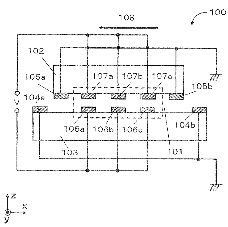
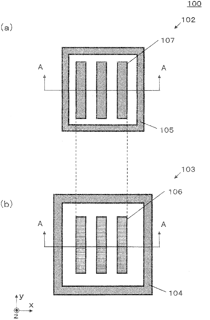
[0071] figure 1 is a cross-sectional view of the vibration power generator 100 according to Embodiment 1 of the present invention, figure 2 yes figure 1 The first substrate 102 of the vibration generator 100 ( figure 2 (a)), and the second substrate 103 ( figure 2 (b)) top view. figure 1 The section shown with the figure 2 The A-A cross-section is equivalent.

[0072] The vibration generator 100 is composed of a first substrate 102 and a second substrate 103 . On the first substrate 102 ( figure 1 Middle, lower side) are formed with first electrodes 107a, 107b, 107c. In addition, on the second substrate 103 ( figure 1 (middle, top) second electrodes 106a, 106b, 106c are formed at positions facing each of the first electrodes 107a, 107b, 107c.

[0073] Third electrodes 105 a and 105 b are further formed on the first substrate 102 , and fourth electrodes 104 a and 104 b are further formed on the second substrate 103 .

[0074] The first electrodes 107a, 107b, ...

Embodiment approach 2

[0132] Figure 5 It is a cross-sectional view of vibration power generator 200 according to Embodiment 2 of the present invention. This differs from Embodiment 1 in that first protrusions 209 a and 209 b are formed between the first substrate 202 and the second substrate 203 .

[0133] Additionally, for Figure 5 Each shown member is given a number with a 200-series number in order to clarify that it is a member according to the present embodiment. Unless otherwise specified, each component is the same as the corresponding component in Embodiment 1 indicated by the same code except for the 100-digit numeral.

[0134] One end of the protrusions 209 a and 209 b is fixed to one of the first substrate 202 and the second substrate 203 , and the other end is not fixedly in contact with the other of the first substrate 202 and the second substrate 203 .

[0135] exist Figure 5 In the illustrated embodiment, one end (lower end) of the protrusions 209a, 2009b is fixed to the secon...

Embodiment approach 3

[0159] Image 6 is a cross-sectional view of the vibration power generator 300 in Embodiment 3 of the present invention ( Image 6 (a)) and the cross-sectional view of the first substrate 302 ( Image 6 (b)).

[0160] The difference from Embodiment 2 is that the vibration power generator 300 has a third substrate 310 disposed above the first substrate, and second protrusions 309 c and 309 d disposed between the third substrate 310 and the first substrate 302 .

[0161] Additionally, for Image 6 Each of the shown members is assigned a numeral with a 300 series number to clarify that it is a member according to the present embodiment. Unless otherwise specified, each component is the same as the corresponding component in Embodiments 1 and 2 indicated by the same code except for the 100-digit numeral.

[0162] In the present embodiment, the first protrusions 309a and 309b are provided with one end fixed to the second substrate 303 and the other end in contact with the lower...


PUM


Abstract

Provided are a vibration power generator, a vibration power generation device, and an electronic device and a communication device having vibration power generation device installed, wherein a complex structure or process is not necessary, mechanical reliability is improved, and lower frequencies can be dealt with. The vibration power generator comprises a first substrate, a first electrode arranged upon the first substrate, a second substrate separated from and facing the first substrate, and a second electrode arranged upon the second substrate. The first substrate can vibrate with respect to the second substrate, and either the first electrode or the second electrode comprises an electric-charge carrying film. The vibration power generator further comprises a third electrode arranged upon the first substrate and containing an electric-charge carrying film, and a fourth electrode arranged upon the second substrate and containing an electric-charge carrying film, and the third and fourth electrodes are arranged so that the first substrate is held at a prescribed position when there is no external force applied thereto, and when there is external force applied to the first substrate and the first substrate is moved with respect to the second substrate, an electrostatic force is applied to return the first substrate to the prescribed position.

Description

technical field [0001] The present invention relates to a kind of vibration power generator and a kind of vibration power generation device, a kind of communication device and electronic equipment loaded with vibration power generation device, especially relate to a kind of electrostatic induction type vibration power generator utilizing electret (electret) material and A vibration power generation device, a communication device and electronic equipment loaded with the vibration power generation device. Background technique [0002] As a conventional vibration power generation device, an electrostatic induction type vibration power generation device is known in which charge is applied to one electrode of a variable capacitor and the charge is induced to the opposite electrode by electrostatic induction. The induced charge is changed by the change of capacitance. An electrostatic induction type vibration power generator extracts this change in electric charge as electric ene...

Claims


Application Information

Patent Timeline
Patent Type & Authority Applications(China)
IPC IPC(8): H02N1/08
CPCH02N1/08
Inventor 中塚宏大西庆治
Owner PANASONIC CORP
Why Eureka
Try Eureka