
Water channel pre-filling method used during lost foam casting of engine cylinder body

A technology of engine cylinder block and lost foam casting, which is applied in the direction of casting molding equipment, molds, mold components, etc. It can solve the problems of channel blockage flow, high labor intensity of workers, and low efficiency, so as to meet the pressure resistance and reduce pressure. The effect of small cleaning workload and reduced labor intensity

Inactive Publication Date: 2012-02-08
CHUZHOU JINNUO INDAL
View PDF5 Cites 0 Cited by
  • Summary
  • Abstract
  • Description
  • Claims
  • Application Information

AI Technical Summary

Problems solved by technology

[0002] When using lost foam casting engine cylinder block, due to the complex shape of the cylinder block, there are many holes inside the cavity, and when using lost foam casting, the rain-type sanding is used, which causes the direction of sanding and some The direction of the channel is vertical, so that the sand in the channel is not in place or cannot be added, resulting in the blockage of the channel or the flow rate is not up to standard. The engine has technical requirements for the flow of the water channel, and the current casting method can easily lead to blockage of the water channel of the cylinder body, resulting in a large amount of cleaning work in the later stage, high labor intensity and low efficiency of the workers, and it is more likely that the flow rate will not meet the standard due to the blockage of the water channel. Cylinder scrapped

Method used


Image

  • Water channel pre-filling method used during lost foam casting of engine cylinder body
  • Water channel pre-filling method used during lost foam casting of engine cylinder body
  • Water channel pre-filling method used during lost foam casting of engine cylinder body

Examples


Embodiment 1

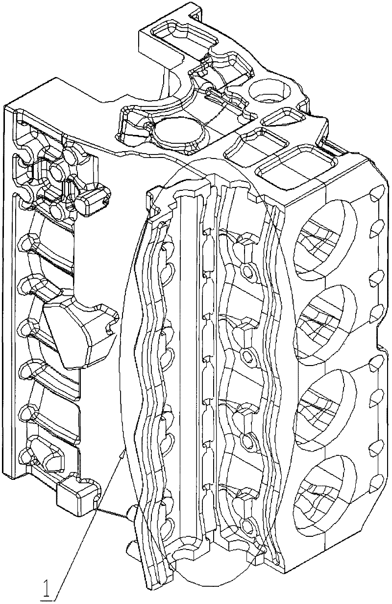
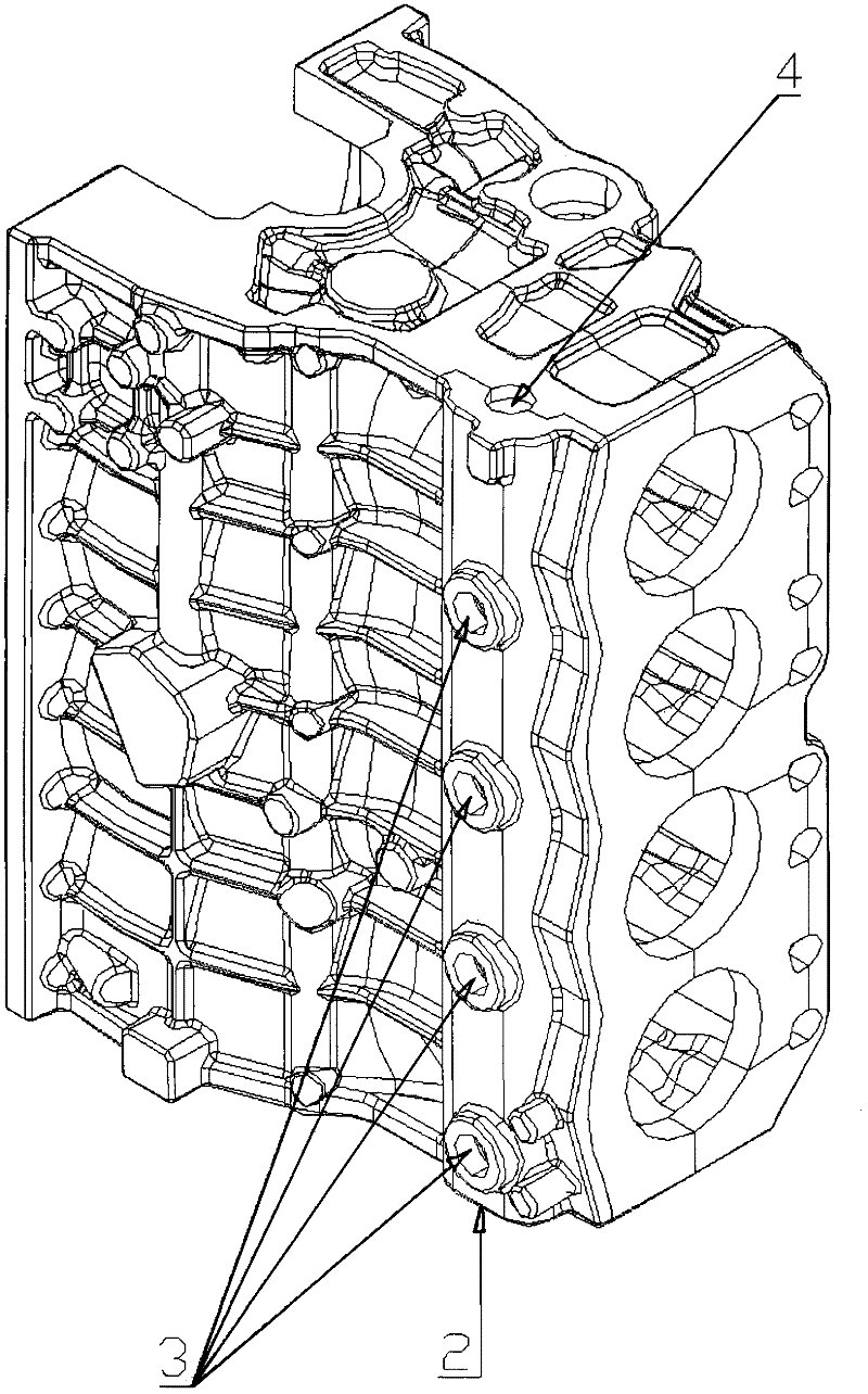
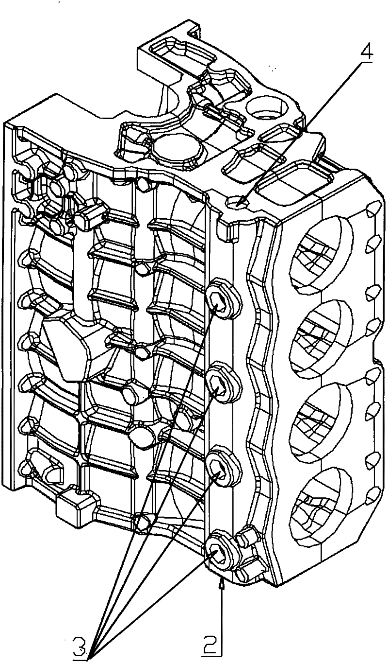
[0023] An existing engine block is cast by the lost foam method, and the lost foam model is ready, and now the water channel is pre-filled. figure 1 shown) on the workbench, and then figure 2 As shown, the lower sealing port 2 of the waterway hole is blocked with glass sand, the side hole 3 of the waterway 1 is sealed with glass cloth and hot melt adhesive, and only one port 4 is left as a sand filling port. ② Put the model in the three-dimensional vibrating sand box, and the lower plugging port 2 of the plugging end is down, so that the direction of the channel hole is consistent with the sand feeding direction, that is, the hole between the lower plugging port 2 and the port 4 is parallel to the sand feeding direction. ③Inject a specified amount of dry sand into the waterway 1 at a constant speed through the port 4 of the waterway 1, and after shaking to the specified compactness, then block the port 4 with water glass sand, so that the waterway becomes a closed state. ④ A...


PUM


Abstract

The invention discloses a water channel pre-filling method used during lost foam casting of an engine cylinder body, relating to the technical field of casting. The water channel pre-filling method comprises the steps of: firstly, placing a bonded lost foam model of a cylinder on a workbench, plugging a lower plugging opening of a water channel hole by using water glass sand, and sealing lateral holes of a water channel by using glass cloth and hot-melt adhesives, wherein only one port is reserved to serve as a sand filling port; placing the model in a three-dimensional vibrating sand box, wherein the lower plugging port at a plugging end is placed at a lower part; injecting dry sand into the water channel, and plugging a sand feeding port by using the water glass and after sand injection is finished, wherein the injection amount of the dry sand is equal to the volume of the water channel; performing modeling and pouring after the water glass sand is self-hardened; and after a casting piece is discharged out of the box, removing the water glass sand after the glass cloth drops automatically, and pouring out the dry sand inside the water channel to obtain a smooth cylinder body water channel. The invention provides the more economic and feasible water channel pre-filling method, the blocking problems of the water channel is solved and the qualification rate of the water channel is increased.

Description

technical field [0001] The invention relates to the field of casting technology, in particular to a method for prefilling water passages during lost foam casting of engine cylinder blocks. Background technique [0002] When using lost foam casting engine cylinder block, due to the complex shape of the cylinder block, there are many holes inside the cavity, and when using lost foam casting, the rain-type sanding is used, which causes the direction of sanding and some The direction of the channel is vertical, so that the sand in the channel is not in place or cannot be added, resulting in blockage of the channel or the flow rate is not up to standard. Among them, the channel is more prominent. The engine has technical requirements on the flow rate of the water channel, and the current casting method can easily lead to clogging of the water channel of the cylinder body, resulting in a large amount of cleaning work in the later stage, high labor intensity and low efficiency of t...

Claims


Application Information

Patent Timeline
Patent Type & Authority Applications(China)
IPC IPC(8): B22C9/04
Inventor 马正松张玉胜徐乔
Owner CHUZHOU JINNUO INDAL
Learn More