
Baby carriage and baby carriage braking mechanism

A technology of brake mechanism and baby carriage, which is applied in the field of brake mechanism and can solve the problems of short service life and low reliability

Active Publication Date: 2013-11-20
WONDERLAND NURSERYGOODS CO LTD
View PDF4 Cites 0 Cited by
  • Summary
  • Abstract
  • Description
  • Claims
  • Application Information

AI Technical Summary

Problems solved by technology

Therefore, this kind of braking mechanism also has the problems of short service life and low reliability.

Method used


Image

  • Baby carriage and baby carriage braking mechanism
  • Baby carriage and baby carriage braking mechanism
  • Baby carriage and baby carriage braking mechanism

Examples


Embodiment Construction

[0040] The present invention will be further described below with reference to the accompanying drawings and preferred embodiments, but the embodiments of the present invention are not limited thereto.

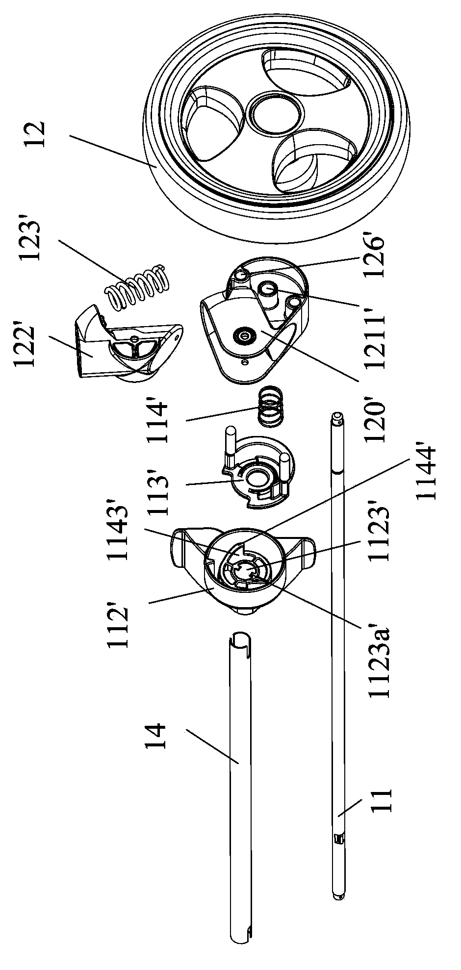
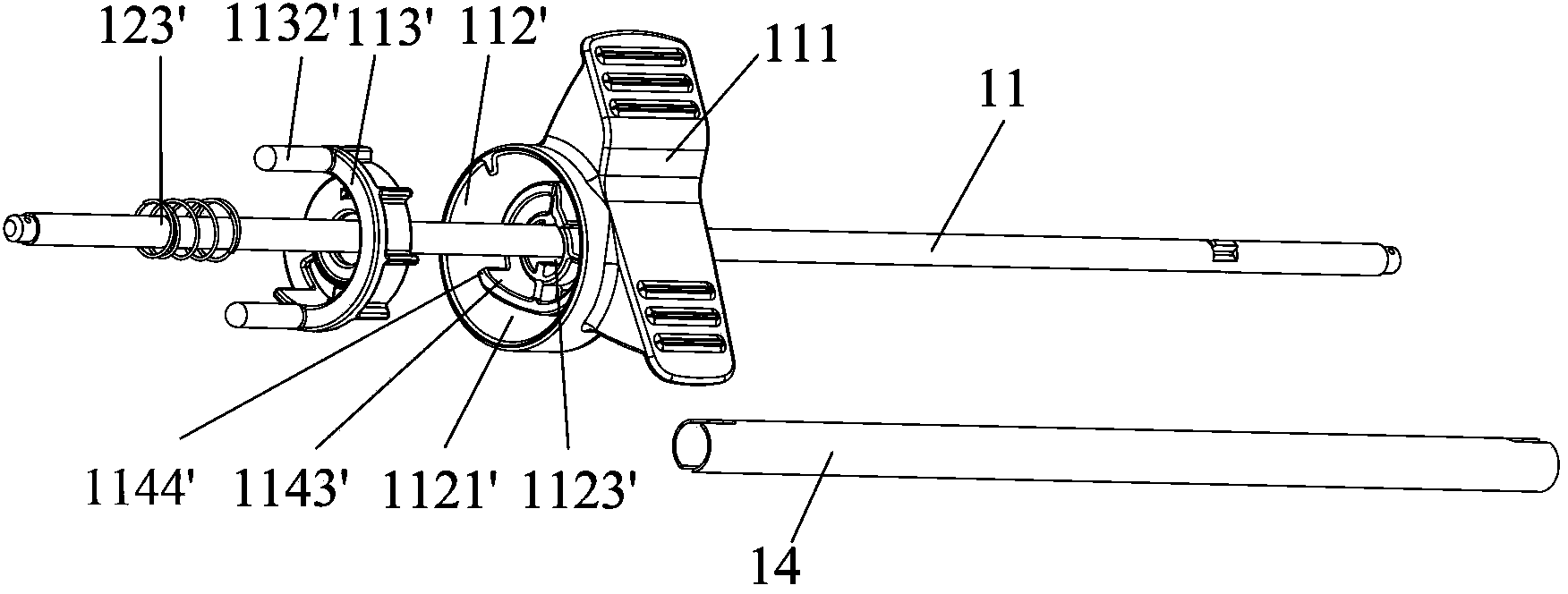
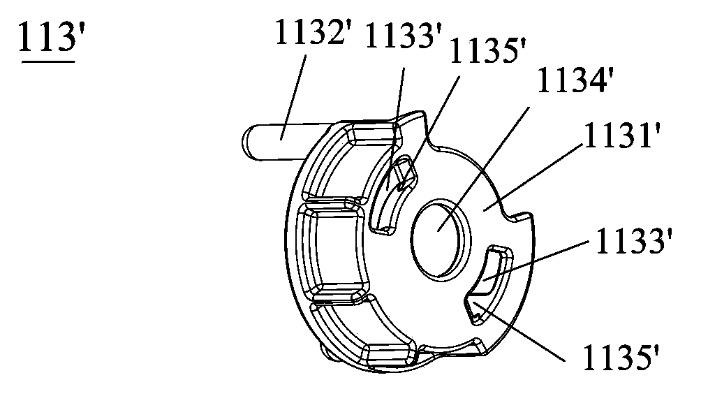
[0041] Please refer to Figure 1-2b The first embodiment of the baby carriage brake mechanism 1 of the present invention includes a wheel shaft 11, a wheel 12, a linkage pipe 14 sleeved outside the wheel shaft 11, and at least one brake that is located inside the wheel 12 and is sleeved on the wheel shaft 11. Fixing seat 100. In the present invention, the inner sides of the two wheels 12 are provided with brake fixing seats 100 respectively. Since the two wheels 12 have the same structure, only one of them will be described in this embodiment.

[0042] Such as Figure 1-3 As shown, the brake fixing seat 100 includes a brake assembly 101 and a fitting fixing seat 120 . Specifically, after the brake fixing seat 100 is assembled, the fixing seat 120 is located between the brak...


PUM


Abstract

A brake mechanism for a stroller includes an axle, a wheel and at least one brake fixing seat disposed at an inner side of the wheel. The brake fixing seat includes a brake assembly and a fixing seat. The brake assembly includes a pedal assembly and a brake member. The brake member has at least one abutting portion and at least one brake arm. The brake assembly includes a pushing member for pushing the abutting portion. A brake hub is disposed at the inner side of the wheel. A plurality of recesses is formed on the brake hub and arranged compactly. The axle passes through the pedal assembly, the brake member, and the fixing seat. The pedal assembly is used to drive the pushing member to push the abutting portion and the brake member moves toward the brake hub until the brake arm extends into the recesses.

Description

technical field [0001] The invention relates to a brake mechanism, in particular to a baby carriage brake mechanism and a baby carriage with the baby carriage brake mechanism. Background technique [0002] Existing baby carriages are generally equipped with braking mechanisms in order to ensure driving safety. Existing braking mechanism great majority is to realize braking by inserting the braking hole on the wheel braking casing by the braking rod that is fixed on the wheel seat. [0003] A traditional braking mechanism includes a wheel located under the vehicle frame, a fixing part arranged on the wheel and a rod part arranged on the vehicle frame. A brake hole is set on the fixed frame, and a brake lever is rotatably arranged on the rod member. The brake lever has a brake position and a brake release position. When the brake lever is in the brake position, the brake lever is located in the brake hole; When the brake position is reached, the brake lever is separated from...

Claims


Application Information

Patent Timeline
Patent Type & Authority Patents(China)
IPC IPC(8): B62B9/08
CPCB62B9/082B62B9/087B62B5/0461B62B5/0433B62B9/08
Inventor 陈瑞斌崔宗旺
Owner WONDERLAND NURSERYGOODS CO LTD
Learn More