
Band-shaped body connection structure

A belt-shaped body and structure technology, which is applied in the direction of conveyors, mechanical conveyors, transportation and packaging, etc., to achieve the effect of keeping the conveying interval constant, simple structure, and reducing manufacturing costs

Active Publication Date: 2014-03-05
MEGALITE IND
View PDF7 Cites 0 Cited by
  • Summary
  • Abstract
  • Description
  • Claims
  • Application Information

AI Technical Summary

Problems solved by technology

Therefore, there is a problem that it is not easy to separate the front and rear assembly carts 91.

Method used


Image

  • Band-shaped body connection structure
  • Band-shaped body connection structure
  • Band-shaped body connection structure

Examples


Embodiment Construction

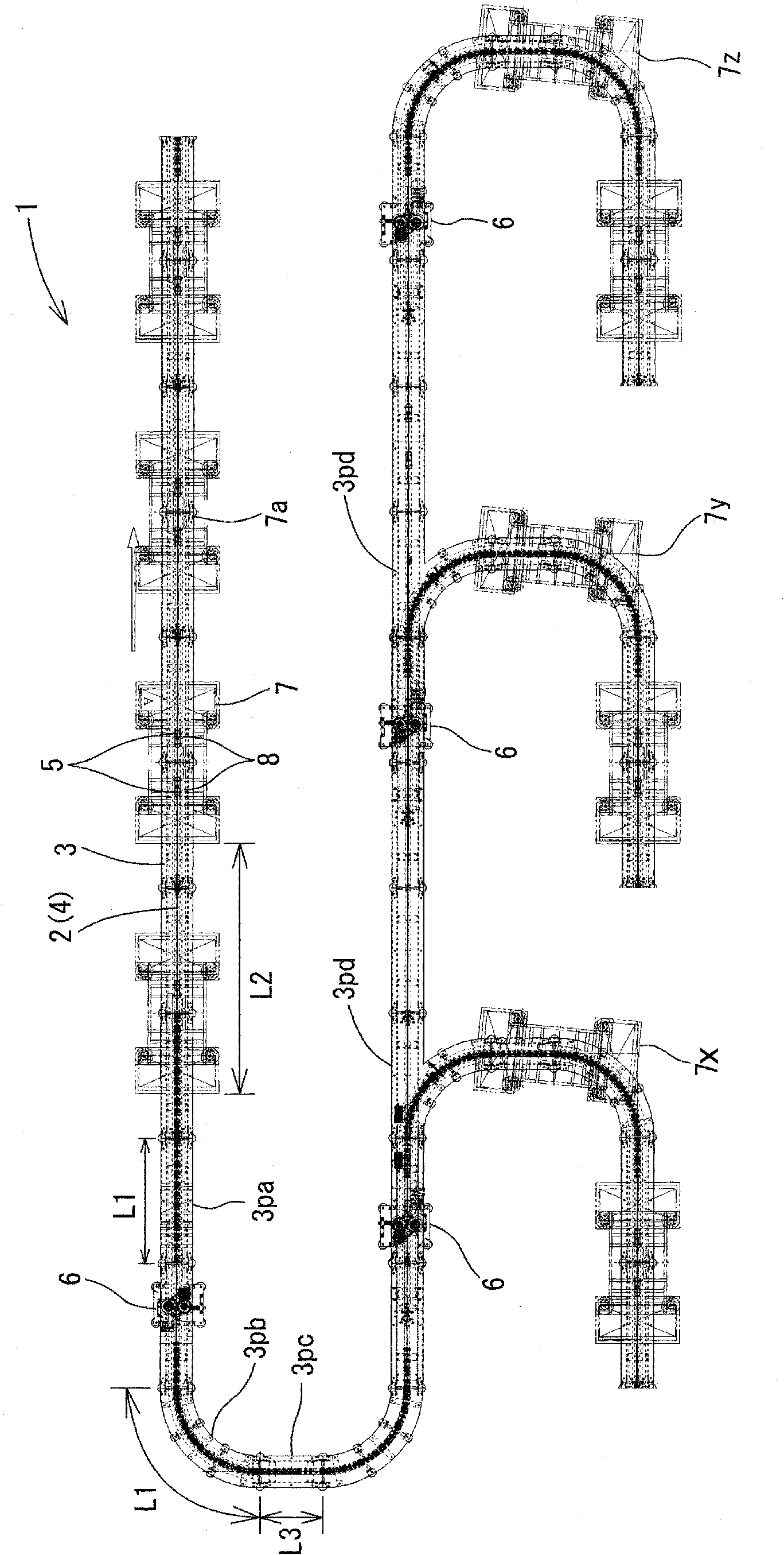
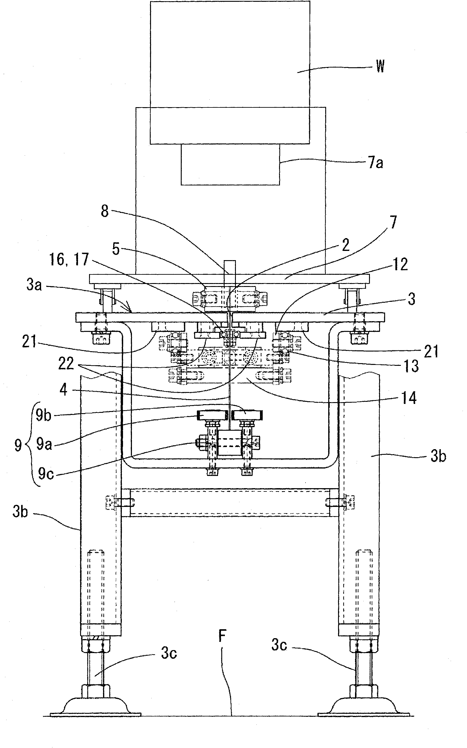
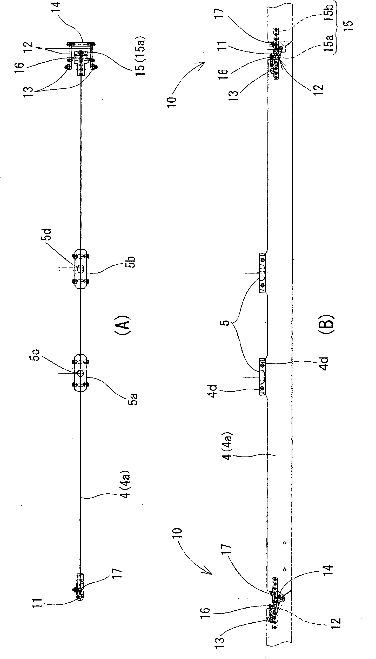
[0030] Below, use Figure 1~Figure 9 The structure of the belt-shaped body connection structure 10 of the present invention will be described. The connecting structure 10 of the belt-shaped body of the present invention constitutes a part of the workpiece conveying device 1. The workpiece conveying device 1 has: a stand 3 formed with a cutout 2; a belt-shaped body 4 whose upper part is housed in the stand 3 in a manner guided by the cutout 2 of the stand 3; The upper end of the belt-shaped body 4 is connected and protrudes from the upper part of the platform 3; the driving part 6, which provides the power to move the belt-shaped body 4 along the incision 2 in the conveying direction; and the assembly trolley 7, which has a support As an example of the work W, a support portion 7 a of an engine or an engine assembly and a connecting portion 8 connected to the trolley connecting portion 5, and the assembly trolley 7 travels on the platform 3.

[0031] The workpiece conveying devi...


PUM


Abstract

The invention provides a band-shaped body connection structure, which is simple in structure and enables a trolley to move in any direction. Meanwhile, assembly trolleys before and after the conveying direction can be easily connected together and separated from each other. The upper part of the band-shaped body connection structure is equipped with a trolley connection part for assembly trolleys. The trolley connection part is accommodated inside a bench by being guided by the cut of the bench. The connection structure comprises a stop pin installed in the end of the band-shaped body before the conveying direction X and capable of moving up and down; and an arm arranged at the end of the band-shaped body behind the conveying direction and capable of freely dumping around a horizontal axis vertical to the conveying direction. The lower end of the arm is equipped with a cam follower and the lower end of the cam is equipped with a stop rod clamped with the stop pin. The lower end of the stop pin is equipped with an inclined surface arranged upwards and toward the conveying direction. The cam follower abuts against the lower surface of a connection maintaining cam formed along the cut of the bench. The arm is inclined in a way to reduce the inclination angle with respect to the horizontal plane. The stop rod is fixed to a height abutting against the surface behind the conveying direction X of the stop pin.

Description

Technical field [0001] The present invention relates to a connection structure of a belt-shaped body used as a power transmission unit in a conveying device of an assembly trolley that conveys a workpiece. Background technique [0002] In the past, assembling carts (assembly jig carts) were used to transport engines, etc. In the conveyor device using this assembly cart, each assembly cart was connected to the conveyor chain, and the chain was arranged along the assembly line. Move, thereby moving each assembly trolley together. [0003] In the chassis preparation production line 90 described in the following Patent Document 1, such as Picture 10 As shown in (A), the assembly trolley 91 carrying the engine and the chassis is moved by the drive chain 92 in a ring configuration, and the assembly work of the engine and the chassis is performed, and the assembled engine assembly is performed by the engine mounting device Installed on the vehicle. [0004] The connecting part of the asse...

Claims


Application Information

Patent Timeline
Patent Type & Authority Patents(China)
IPC IPC(8): B65G35/00
Inventor 中村健生
Owner MEGALITE IND
Learn More