Anti-static high-holding-force elastic card clothing and forming process thereof

A holding force and anti-static technology, applied in fiber processing, deburring devices, textiles and papermaking, etc., can solve the problems of reduced carding efficiency, influence of cloth quality, entanglement of yarn jitter amplitudes, etc., to avoid tilting or High frequency jitter, the effect of improving mating reliability

Active Publication Date: 2022-08-02
金轮针布(江苏)有限公司
View PDF6 Cites 0 Cited by
  • Summary
  • Abstract
  • Description
  • Claims
  • Application Information

AI Technical Summary

Problems solved by technology

During the actual application of the carding machine, the following problems were found: 1) During the process of yarn being carded, the fine yarn debris is bound to be peeled off from the surface due to the friction force, and then it is very easy to adhere to the U-shaped steel needle In addition, fine yarn scraps will be filled in the gaps formed between the U-shaped steel needles. In severe cases, carding may even occur due to insufficient exposed length of the comb teeth. The operation failed, and it was difficult to carry out the subsequent needle copying operation. The reason is that during the carding process, the U-shaped steel needle accumulated a large amount of static charge in it due to the continuous friction force, and the fine yarn scraps were firmly attached to the surface due to electrostatic induction. Elastic card clothing; 2) It is difficult to guarantee the direction accuracy of a single yarn after carding, and the parallelism and spacing of two adjacent yarns exceed the standard, which is not conducive to the subsequent weaving or gluing of the yarn into cloth. Cloth operation, and the quality of the cloth will also be affected. The reason is that the working outer diameter of the comb teeth of the U-shaped steel needle with fine yarn scraps attached is bound to be greater than the theoretical design outer diameter (increased in disguise) , and along its length direction, according to the specific layer thickness of the attached fine yarn scraps, the value of its working outer diameter is not fixed
In addition, during the combing process, the comb teeth on the U-shaped steel needles will inevitably be subjected to lateral pulling force, and the U-shaped steel needles are inserted on the base fabric with excellent elasticity. The above two factors will inevitably lead to U-shaped steel needles. Shaped steel needles perform reciprocating high-frequency yaw motion, which can easily lead to the occurrence of entanglement between yarns due to excessive vibration amplitude

Method used


Image

  • Anti-static high-holding-force elastic card clothing and forming process thereof
  • Anti-static high-holding-force elastic card clothing and forming process thereof
  • Anti-static high-holding-force elastic card clothing and forming process thereof

Examples


Embodiment 1

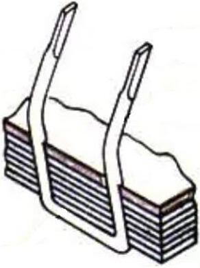
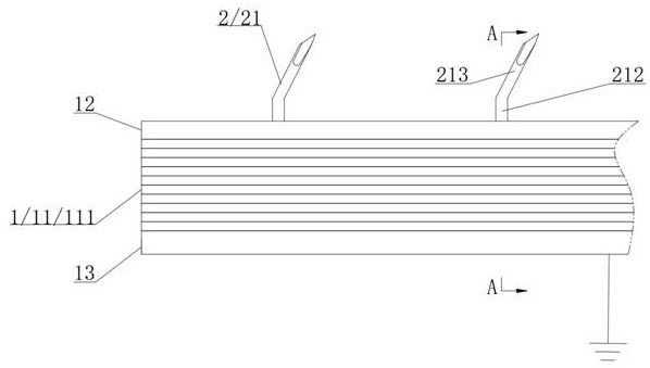
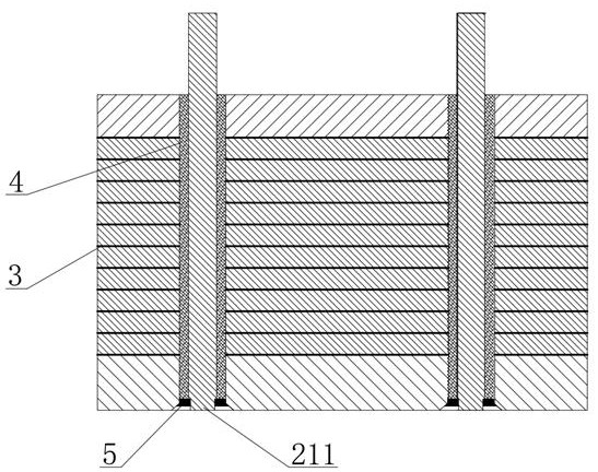
[0048] figure 2 , image 3 The schematic diagram of the structure of the first embodiment of the anti-static high-grip elastic card clothing in the present invention and its A-A cross-sectional view are respectively shown. It can be seen that it is mainly composed of a plate-shaped base 1, a carding component 2, A colloid layer 3, B glue The sleeve 4 and the solder joints 5 are composed of several parts. The combing assembly 2 is composed of a plurality of conductive metal comb needles 21 that are inserted into the plate-shaped base body 1 . The plate-shaped base body 1 includes a fabric composite layer 11 , an oil-resistant plate 12 and a conductive metal plate 13 . Wherein, the fabric composite layer 11 is formed by stacking 6 to 9 layers of burlap 111 . The oil-resistant plate 12 is glued to the upper side of the fabric composite layer 11 and is passed through by the conductive metal comb needles 21 . The conductive metal plate 13 is glued to the lower side of the fabr...

Embodiment 2

[0058] Figure 4 , Figure 5 The schematic diagram of the structure of the second embodiment of the anti-static high-holding force elastic card clothing in the present invention and its partial enlarged view are respectively shown. It can be seen that the difference between the second embodiment and the first embodiment is that the conductive metal The difference in soldering method between the comb pin 21 and the conductive metal plate 13 is specifically: the conductive pin 211 is in the shape of a flat strip, which is directly extended downward from the lower knee section 212 . A strip-shaped accommodating groove 131 that is adapted to the shape of the conductive pins 211 extends inward from the outer sidewall of the conductive metal plate 13 . After the conductive metal pins 21 are inserted in place relative to the mating holes, a 90° bending operation is performed on the conductive pins 211 to flatly press them in the strip-shaped receiving grooves 131 , and then along th...


PUM

PropertyMeasurementUnit
thicknessaaaaaaaaaa
thicknessaaaaaaaaaa

Abstract

The invention relates to anti-static high-holding-force elastic card clothing which comprises a plate-shaped base body and a carding assembly. The carding assembly is composed of a plurality of conductive metal card wires inserted into the plate-shaped base body in a matched mode. The plate-shaped base body comprises a fabric composite layer, an oil-resistant plate and a conductive metal plate. And the oil-resistant plate and the conductive metal plate are respectively glued on two sides of the fabric composite layer. And the conductive metal plate and the tail end of each conductive metal card wire are kept in an electric connection state. Thus, on one hand, it can be guaranteed that static charges gathered on the conductive metal card wires can be conducted out in time, and then the phenomenon that stripped fine yarn scraps are attached to the conductive metal card wires or fill installation gaps of the conductive metal card wires due to electrostatic induction is prevented; on the other hand, the oil-resistant plate and the conductive metal plate can synergistically play an auxiliary supporting role on the conductive metal card wires, and it is guaranteed that the conductive metal card wires are always kept in a correct posture in the yarn combing process. In addition, the invention further relates to a forming process for preparing the anti-static high-holding-force elastic card clothing.

Description

technical field [0001] The invention relates to the technical field of textile equipment manufacturing, in particular to an anti-static high-holding elastic card clothing and a molding process thereof. Background technique [0002] Card clothing is one of the core parts of the carding machine. It is wrapped on the drum to form a flat and sharp needle surface, which is used for carding fibers, and can also be used for opening and removing impurities. According to the different processing requirements of spinning raw materials, elastic card clothing and rigid card clothing can be appropriately selected. [0003] In the prior art, such as figure 1 As shown in , the elastic card clothing is mainly composed of a base cloth and a U-shaped steel needle. The U-shaped steel needle is made of high-carbon steel wire bent and inserted longitudinally on the base fabric. The base fabric is required to be firm and elastic. The base fabric is generally made of 3 to 9 layers of fabrics...

Claims


Application Information

Patent Timeline
Patent Type & Authority Applications(China)
IPC IPC(8): D01G15/84D01G15/86D01G15/88C25D5/14C25D5/36C25D5/48C25D7/00C25F1/00C25F3/06
CPCD01G15/84D01G15/86D01G15/88C25D7/00C25D5/36C25F1/00C25F3/06C25D5/14C25D5/48Y02P70/62
Inventor 卓城之陆忠顾炜华金磊磊贾丙勇高勤超
Owner 金轮针布(江苏)有限公司
Why Eureka
Try Eureka