Flowerpot-type protective device and manufacturing method thereof

A technology for protective devices, flower pots, applied in the direction of door/window protection devices, botany equipment and methods, building construction, etc.

Inactive Publication Date: 2012-02-08
张朝峰
View PDF4 Cites 10 Cited by
  • Summary
  • Abstract
  • Description
  • Claims
  • Application Information

AI Technical Summary

Problems solved by technology

[0003] In order to solve the above-mentioned shortcomings, the object of the present invention is to provide a flowerpot-type protection device with beautiful appearance, which can plant flowers and plants, and which can automatically alarm when it is invaded by climbing, theft, etc., and does not need to cover the window, does not affect lighting, and can It is convenient to enter and exit from inside and outside, without endangering the existing buildings. The window acts as a safe evacuation channel, which solves the shortcomings of the existing protective devices.

Method used


Image

  • Flowerpot-type protective device and manufacturing method thereof
  • Flowerpot-type protective device and manufacturing method thereof
  • Flowerpot-type protective device and manufacturing method thereof

Examples


Embodiment 1

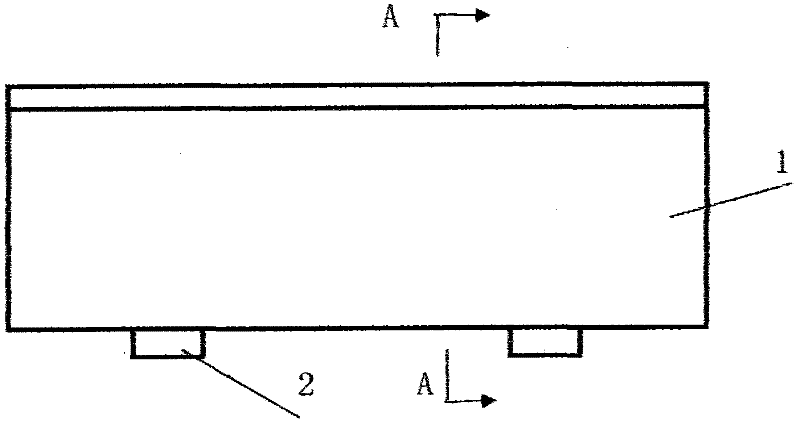
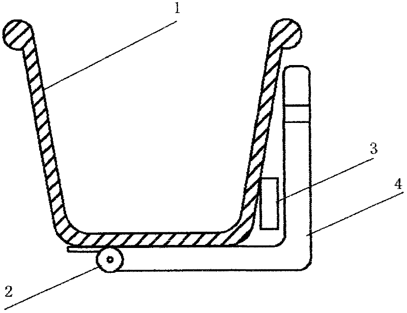
[0015] Embodiment 1: as figure 1 , figure 2 : A flower pot type protection device, mainly composed of a pot body 1 and an electronic switch 3, extruded with a mold to form a long groove, (reference size: upper mouth 15-25cm, lower bottom 10-15cm, height 10-20cm), Cut the corresponding length according to the width of the window to make a rectangular basin 1; make an "L"-shaped mounting plate 4 by bending a metal plate, one end of the mounting plate 4 is fixed to the elastic hinge 2, and one or two mounting holes are drilled at the other end; the bottom of the basin 1 Fixed with the elastic hinge 2, the outer edge of the elastic hinge 2 is flush with the outer edge of the bottom of the basin body 1, so that most of the bottom of the basin body 1 bears pressure on the mounting plate 4; a wireless door sensor with a mercury switch is installed on the inside of the basin body 1 Launcher 3, respectively fix two mounting plates 4 on the wall outside the window with expansion screw...

Embodiment 2

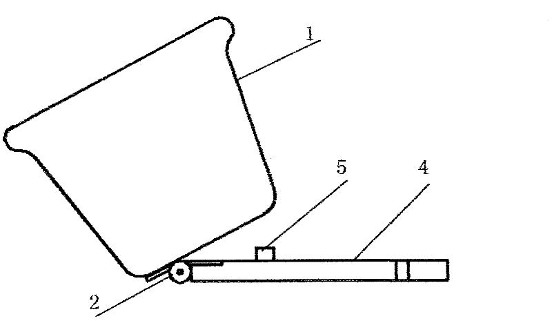
[0016] Embodiment 2: as image 3 : Make a rectangular basin body 1 by mold injection molding or stamping (reference size: upper mouth 18-25cm, bottom width 10-15cm, height 10-20cm, length 50cm, 60cm, 70cm, 80cm and 90cm five specifications); use metal Make a "one"-shaped mounting plate 4, and set a button switch 5 inside at least one of the mounting plates 4. The button of the button switch 5 protrudes from the plane of the mounting plate 4; one end of the mounting plate 4 is fixed with the elastic hinge 2, and the other end is drilled. There are one or two installation holes; the bottom of the basin body 1 is fixed with the elastic hinge 2, the outer edge of the elastic hinge 2 is flush with the outer edge line of the bottom of the basin body 1, most of the bottom of the basin body 1 bears pressure on the installation plate 4, and presses down The button of the button switch 5; fix the two mounting plates 4 on the window sill with expansion screws (several mounting plates can...


PUM


Abstract

The invention provides a flowerpot-type protective device and a manufacturing method thereof, and belongs to the field of anti-creep and anti-theft devices for walls, balconies and windows of buildings. The flowerpot-type protective device mainly comprises a pot body and an electronic switch, and is characterized in that an elastic hinge is arranged on the bottom of the rectangular pot body, the other side of the elastic hinge is fixed on a horizontal line-shaped or L-shaped mounting plate, and the mounting plate is equipped with mounting holes; and the electronic switch is arranged inside the pot body and is connected with alarm equipment. The flowerpot-type protective device is arranged on a windowsill or outside a window, and flower and grass can be planted in the device; and when the pot body is pulled to rotate at a certain angle in case of external creeping force, the electronic switch is turned on and then the alarm equipment gives out an alarm, thus achieving an anti-theft protection effect and facilitating escape and relief.

Description

technical field [0001] The invention belongs to anti-climbing and anti-theft devices for walls, balconies, and windows of buildings, and in particular relates to a flowerpot-type protective device capable of planting flowers and plants and a manufacturing method thereof. Background technique [0002] The balconies and windows of existing buildings basically use fence-type anti-theft windows as shrouded protection and anti-theft. Although they can play an anti-theft role, there are also multiple disadvantages: first, the guardrail is not strong, and thieves are easy to kill in a few minutes. Cut, pull off, etc. to destroy, and then sneak in to steal; second, the fence often becomes a tool for thieves to climb buildings, causing safety threats or property loss or even life injury to upper-level residents, thus causing conflicts among neighbors and affecting social harmony. ; the 3rd, if this barrier-type protective device is installed outside the building wall of bottom floor,...

Claims


Application Information

Patent Timeline
Patent Type & Authority Applications(China)
IPC IPC(8): E06B9/00A01G9/02
Inventor 张朝峰
Owner 张朝峰
Why Eureka
Try Eureka