Resonance drive type piezoelectric pump

A piezoelectric pump and driven technology, which is applied in the direction of pumps, pump components, machines/engines, etc., can solve the problems of large fluid flow damping, difficult heat, slow valve movement, etc., to achieve amplification and alternating deformation, good heat dissipation, Effect of high output flow and output pressure performance

Inactive Publication Date: 2012-02-08
JILIN UNIV
View PDF5 Cites 21 Cited by
  • Summary
  • Abstract
  • Description
  • Claims
  • Application Information

AI Technical Summary

Problems solved by technology

[0003] When the existing piezoelectric pump transports gas, because the piezoelectric vibrator is in a closed space, the heat generated by its own vibration is difficult to release, so the heat is serious, which in turn reduces the output efficiency and deteriorates the transport performance, etc. It is not suitable for transporting gas; when transporting fluid with high viscosity, due to the large damping o

Method used


Image

  • Resonance drive type piezoelectric pump
  • Resonance drive type piezoelectric pump
  • Resonance drive type piezoelectric pump

Examples


Embodiment Construction

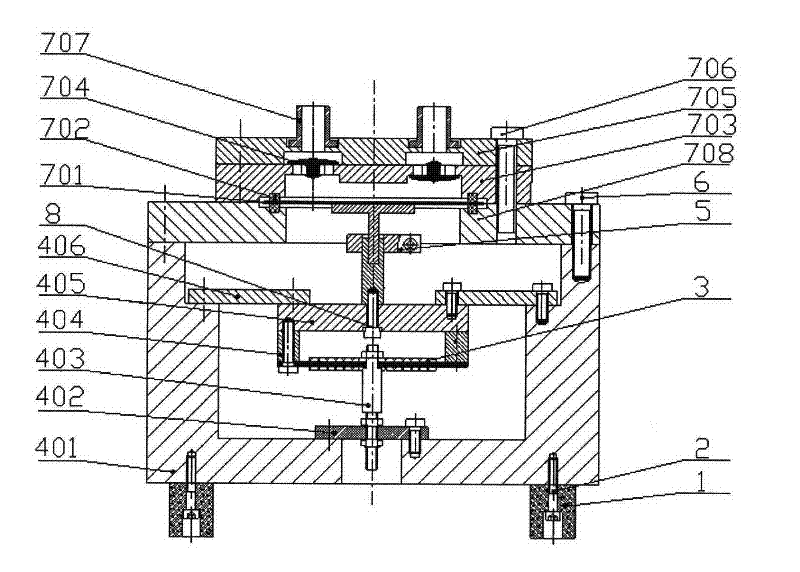
[0017] The structure and principle of the present invention will be further described in the following embodiments in conjunction with the accompanying drawings.

[0018] refer to figure 1 , the piezoelectric pump of the present invention consists of a piezoelectric vibrator 3 that converts electrical energy into mechanical energy as a driving force source, and forms a resonance system together with a resonance amplification mechanism 4, a vibration transmission mechanism 5, a fluid driving mechanism 7, and a driven fluid. The base 401 is supported on the ground by four shock absorbing blocks 1 . The piezoelectric vibrator 3 is connected with the resonant amplifying mechanism 4, and the specific connection method is as follows: in the lower part, the piezoelectric vibrator is connected to the base 401 through the vibration transmission rod 403 and the elastic adjustment piece 402; in the upper part, the piezoelectric vibrator is connected through the connecting ring 404, The ...


PUM


Abstract

The invention discloses a novel piezoelectric pump, wherein a piezoelectric vibrator 3 is used as a drive force source, and forms a resonance system together with a resonance amplification mechanism 4, a resonance transmission mechanism 5, a fluid drive mechanism 7, a driven fluid and the like. Under an external alternating voltage, the deformation of the piezoelectric vibrator 3 acts on the driven fluid after being amplified through the resonance of the system, therefore, the one-way transmission of the fluid is realized. The piezoelectric vibrator 3 can adopt a general dual-wafer bending vibrator structure or single-wafer bending vibrator structure (seen in a picture 2), and can also adopt a single-wafer vibrator, dual-wafer vibrator parallel-connection or serial-connection combined structure.

Description

technical field [0001] The invention belongs to the field of fluid delivery, and in particular relates to a resonance-driven piezoelectric fluid delivery device. Background technique [0002] Piezoelectric pumps are fluid delivery devices that use piezoelectric vibrators as the driving force source. They generally have the advantages of small size, low power consumption, low cost, no electromagnetic interference, and precise flow control. They are used in biomedicine, precision chemistry, micro-electromechanical Engineering and other collars have a wide range of applications. [0003] When the existing piezoelectric pump is transporting gas, because the piezoelectric vibrator is in a closed space, the heat generated by its own vibration is difficult to release, so the heat is serious, which in turn reduces the output efficiency and deteriorates the transport performance. It is not suitable for transporting gas; when transporting fluid with high viscosity, due to the large f...

Claims


Application Information

Patent Timeline
IPC IPC(8): F04B43/04F04B53/00
Inventor 杨志刚刘勇吴越王龙田丰君
Owner JILIN UNIV
Why Eureka
Try Eureka