
Flow collecting valve and crane hydraulic control system with the same

A technology of confluence valve and control oil port, which is applied in the field of crane hydraulic control system and confluence valve, can solve the problems of not effectively reducing energy loss, the pressure does not reach the overflow valve, and the pressure is small, so as to reduce energy consumption. , to ensure the effect of energy consumption and efficiency

Active Publication Date: 2012-02-08
XUZHOU HEAVY MASCH CO LTD
View PDF7 Cites 22 Cited by
  • Summary
  • Abstract
  • Description
  • Claims
  • Application Information

AI Technical Summary

Problems solved by technology

[0013] One situation is that the pressure generated by the large cavity of telescopic oil cylinder 3 is small, and the pressure does not reach the set value of the relief valve after being transmitted to the small cavity. At this time, the flow loss is equal to the flow rate and The product of the difference in flow into the small cavity and the pressure
[0014] Another situation is that the pressure generated by the large chamber of the telescopic oil cylinder 3 is relatively high, and the pressure reaches the setting value of the relief valve after being transmitted to the small chamber. The product of the difference in flow into the small chamber and the setting of the relief valve
[0015] It can be seen that the control method of this asymmetric valve stem can only play a certain role when the retracting pressure is lower than the setting pressure of the retracting relief valve. When the retracting pressure reaches the setting pressure of the retracting secondary relief valve value, its energy consumption is the same as that of double-pump confluence, and it still cannot effectively reduce energy consumption loss

Method used


Image

  • Flow collecting valve and crane hydraulic control system with the same
  • Flow collecting valve and crane hydraulic control system with the same
  • Flow collecting valve and crane hydraulic control system with the same

Examples


Embodiment Construction

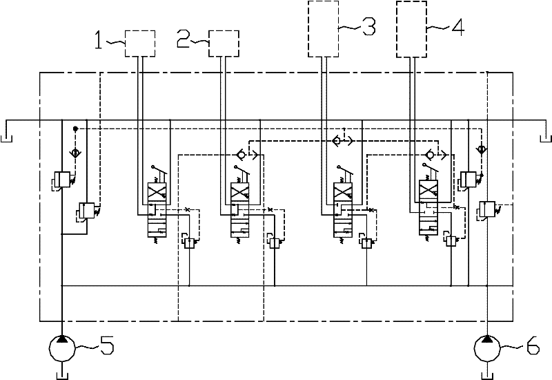
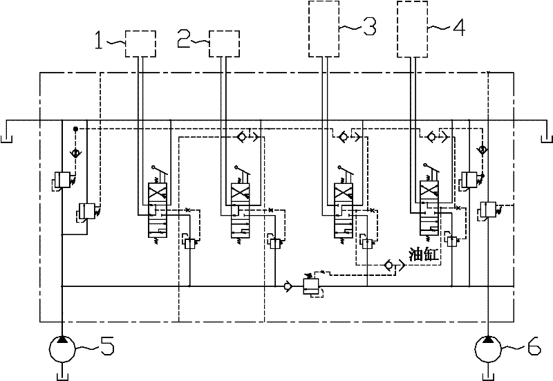
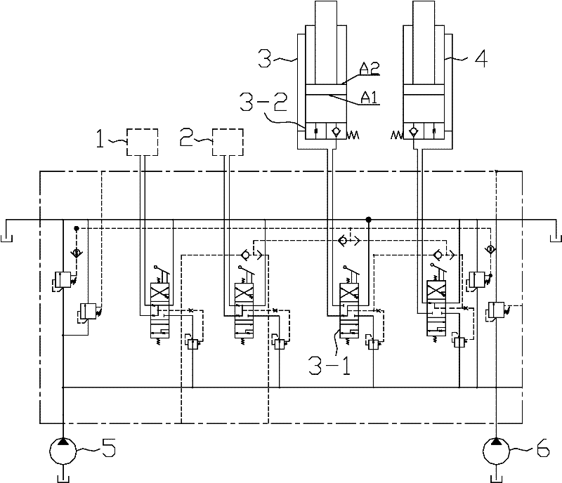
[0047] The core of the present invention is to provide a confluence valve. The merging valve can ensure that the telescopic oil cylinder and the luffing oil cylinder of the crane have both high extension efficiency and low retraction energy consumption.

[0048] Another core of the present invention is to provide a crane hydraulic control system provided with the confluence valve.

[0049] In order to enable those skilled in the art to better understand the solution of the present invention, the present invention will be further described in detail below in conjunction with the accompanying drawings and specific embodiments.

[0050] In this article, terms such as "up, down, left, right" indicating orientation are based on the positional relationship of the drawings, and should not be interpreted as an absolute limitation on the scope of protection. Similarly, terms such as "first, second" It is only for the convenience of description to distinguish different components with ...


PUM


Abstract

The invention discloses a flow collecting valve, comprising the following components: a first shuttle valve; a solenoid valve comprising a first oil port and a second oil port, wherein the first oil port is connected with an oil outlet of the first shuttle valve; a first hydraulic control reversing valve comprising the first oil port and the second oil port, wherein the first hydraulic control reversing valve controls the oil ports to connect with the second oil port of the solenoid valve; and a hydraulic control valve comprising the first oil port and the second oil port, wherein the hydraulic control valve controls the oil ports to connect with the second oil port of the solenoid valve, and has two working states, at the first working state, the first oil port and the second oil port ofthe hydraulic control valve are disconnected, and at the second working state, the first oil port and the second oil port of the hydraulic control valve are communicated. The flow collecting valve can ensure that a telescopic oil cylinder and a luffing oil cylinder of the crane both have higher extension efficiency and lower retraction energy consumption. The invention further discloses a crane hydraulic control system with the flow collecting valve.

Description

technical field [0001] The invention relates to the technical field of engineering machinery, in particular to a confluence valve applied to a hydraulic control system of a crane. The invention also relates to a crane hydraulic control system provided with the confluence valve. Background technique [0002] At present, in truck cranes, the main actions are main hoisting, auxiliary hoisting, telescopic, luffing, and slewing, and the first four actions are generally integrated on the main valve (called multi-way valve). The core component of the control system, which determines the efficiency of the four major actions of the main hoist, auxiliary hoist, telescopic and luffing, and the energy consumption level of the whole machine. [0003] The control methods of the main hoist and the auxiliary hoist of the existing crane are relatively unified, both of which are double-pump confluence, that is, when performing an action, the first oil pump and the second oil pump supply oil ...

Claims


Application Information

Patent Timeline
IPC IPC(8): F16K11/24B66C13/20B66C23/693B66C23/82
Inventor 史先信刘邦才王清送胡小冬
Owner XUZHOU HEAVY MASCH CO LTD
Features
  • Generate Ideas
  • Intellectual Property
  • Life Sciences
  • Materials
  • Tech Scout
  • Unparalleled Data Quality
  • Higher Quality Content
  • 60% Fewer Hallucinations
Learn More