
Excavator operation tool confluence control system and excavator

A work tool and control system technology, applied in the field of hydraulic excavators, can solve the problems of inability to improve the work efficiency of the whole machine, waste of hydraulic oil energy, etc., and achieve the effect of improving work efficiency and energy utilization rate

Active Publication Date: 2021-08-24
SHANDONG LINGONG CONSTR MACHINERY
View PDF7 Cites 0 Cited by
  • Summary
  • Abstract
  • Description
  • Claims
  • Application Information

AI Technical Summary

Problems solved by technology

However, in the actual working conditions of the excavator, there are situations where the action of the working tool 1' and other actions need to be performed at the same time. When performing work tool 1' movement and boom movement, such as figure 2 As shown, the pilot oil controls the first three-position eight-way reversing valve 2' to be in the right position, the pilot oil passes through the oil circuit 100' to control the central bypass valve 3' to be in a closed state, and the oil in the second hydraulic pump 4' passes through The oil circuit and the second three-position eight-way reversing valve 5' enter the boom cylinder 6' for action; although the excavator is in the confluence working mode, the second three-position eight-way reversing valve 5' closes the central oil circuit 300 'As a result, no oil passes through the converging oil circuit 200', and it is in a "false converging state", which actually cannot improve the working efficiency of the whole machine. If the second three-position eight-way reversing valve 5' is in an overflow state at this time, the hydraulic oil will pass through Relief valve overflow causes energy waste

Method used


Image

  • Excavator operation tool confluence control system and excavator
  • Excavator operation tool confluence control system and excavator
  • Excavator operation tool confluence control system and excavator

Examples


Embodiment 1

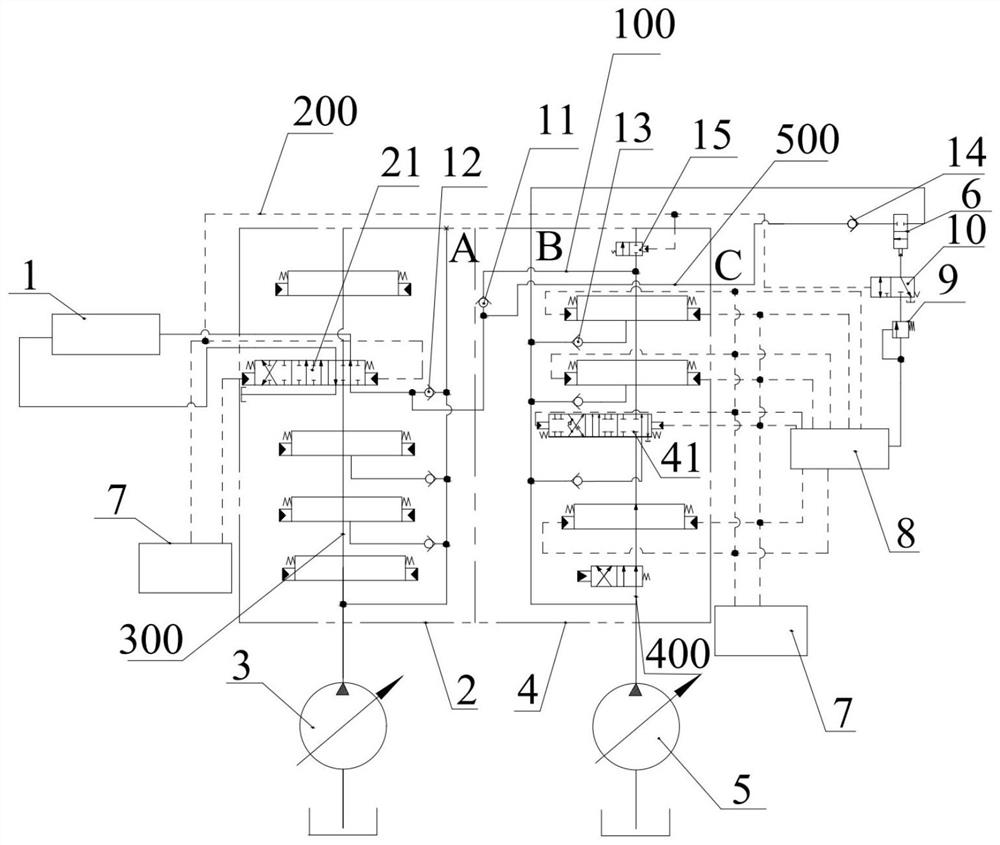
[0048] Such as Figure 3 ~ Figure 5 As shown, the present embodiment provides an excavator work tool confluence control system, the excavator work tool confluence control system includes a work tool driver, a first valve group 2, a first hydraulic pump 3, a second valve group 4, The second hydraulic pump 5 , the confluence oil circuit 100 and the second reversing valve 6 . The working tool 1 can be a bucket, a breaker, a hydraulic shear, a hydraulic pliers, or a grab bucket, so as to perform excavation, crushing, shearing, pinching, or grabbing. The working tool driving part is drivingly connected with the working tool 1, and the working tool driving part drives the working tool 1 to act. The first valve group 2 includes a first reversing valve 21, and the first reversing valve 21 communicates with the driving member of the working tool; the first hydraulic pump 3 communicates with the first reversing valve 21, and is configured to be able to pass through the first reversing ...

example 1

[0063] In this example, one of the multiple reversing valves in the second valve group 4 is the boom reversing valve 41, the boom cylinder 16 is drivingly connected to the boom, and the boom reversing valve 41 communicates with the boom cylinder 16 , the oil outlet of the second reversing valve 6 is directly connected with the oil port C, the oil inlet of the second reversing valve 6 is connected with the oil port B, and the oil port A is blocked; the shuttle valve group 8 includes the boom shuttle valve 81 , two ends of the boom shuttle valve 81 are connected to the pilot oil circuit at both ends of the boom reversing valve 41 , and the other end is connected to the sequence valve 9 .

[0064] Such as image 3 and Figure 4 As shown, when the excavator is in the merged working mode, and the boom and the working tool 1 work at the same time, the hydraulic oil in the second hydraulic pump 5 is divided into two paths, and one path enters the boom cylinder 16 through the boom reve...

example 2

[0067] In this example, one of the multiple reversing valves in the second valve group 4 is the boom reversing valve 41, the boom cylinder 16 is drivingly connected to the boom, and the boom reversing valve 41 communicates with the boom cylinder 16 , the oil outlet of the second reversing valve 6 is directly connected with the oil port A, the oil inlet of the second reversing valve 6 is connected with the oil port B, and the oil port C is blocked; the shuttle valve group 8 includes a boom shuttle valve 81 , two ends of the boom shuttle valve 81 are connected to the pilot oil circuit at both ends of the boom reversing valve 41 , and the other end is connected to the sequence valve 9 .

[0068] Such as image 3 and Figure 5 As shown, when the excavator is in the confluence mode, and the boom and the work tool 1 work at the same time, the hydraulic oil in the second hydraulic pump 5 is divided into two paths, and one path enters the boom cylinder 16 through the boom reversing v...


PUM


Abstract

The invention discloses an excavator operation tool confluence control system and an excavator, and belongs to the technical field of hydraulic excavators. When the excavator is in the confluence working mode, a first hydraulic pump supplies oil to an operation tool driving part through a first reversing valve, and the operation tool driving part drives an operation tool to act. When action execution assemblies connected with reversing valves in a second valve group do not act, second reversing valves are closed, a second hydraulic pump supplies oil to the operation tool driving part through the reversing valves and a confluence oil way, and confluence is achieved; and when the action executing assembly connected with one reversing valve in the second valve group acts, the second reversing valve is opened, the second hydraulic pump supplies oil to the action executing assembly and supplies oil to the operation tool driving part through the second reversing valve at the same time, and confluence is achieved. According to the excavator operation tool confluence control system and the excavator, confluence can be achieved under any condition, and the working efficiency and the energy utilization rate of the excavator are greatly improved.

Description

technical field [0001] The invention relates to the technical field of hydraulic excavators, in particular to an excavator operation tool confluence control system and an excavator. Background technique [0002] An excavator is an earth-moving machine that uses a bucket to excavate materials above or below the bearing surface, and loads them into a transport vehicle or unloads them to a stockpiling plant. In terms of the development of construction machinery in recent years, the development of excavators is relatively fast, and excavators have become one of the most important construction machinery in engineering construction. In order to realize the purpose of the excavator to perform tasks under various working conditions, more and more working tools are installed on the excavator, so that it can not only realize the excavation function, but also realize various functions such as crushing, shearing, pinching, grabbing, etc. Features. In order to meet the use requirements...

Claims


Application Information

Patent Timeline
Patent Type & Authority Applications(China)
IPC IPC(8): E02F9/22
CPCE02F9/22E02F9/2264E02F9/2267E02F9/2292
Inventor 苗国华李强范锦龙孙冬冬
Owner SHANDONG LINGONG CONSTR MACHINERY
Features
  • Generate Ideas
  • Intellectual Property
  • Life Sciences
  • Materials
  • Tech Scout
  • Unparalleled Data Quality
  • Higher Quality Content
  • 60% Fewer Hallucinations
Learn More