Endoscope technology-based discharge-trace inspection system

A technology for discharge traces and inspection systems, which can be used in CCTV systems, fault locations, etc., to solve problems such as omissions, wasted time, and long distances in inspection work.

Inactive Publication Date: 2012-02-08
STATE GRID HENAN ELECTRIC POWER COMPANY ANYANG POWER SUPPLY
View PDF6 Cites 8 Cited by
  • Summary
  • Abstract
  • Description
  • Claims
  • Application Information

AI Technical Summary

Problems solved by technology

[0002] When the power transmission and transformation lines encounter lightning strikes, short-circuits or flashovers of foreign objects, discharge traces will be left on the short-circuit or ground discharge points. When looking for points, there are many blind spots, which cause omissions in the inspection work
In many cases, because the discharge point cannot be found, the power must be cut off for maintenance, wasting a lot of time
[0003] The application number is 200910251260.5, and the inventi...

Method used


Image

  • Endoscope technology-based discharge-trace inspection system
  • Endoscope technology-based discharge-trace inspection system
  • Endoscope technology-based discharge-trace inspection system

Examples


Embodiment 1

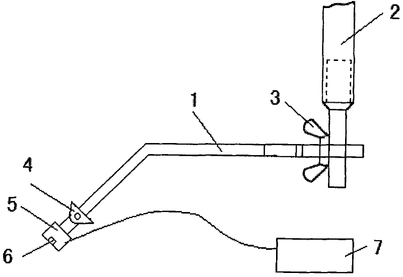
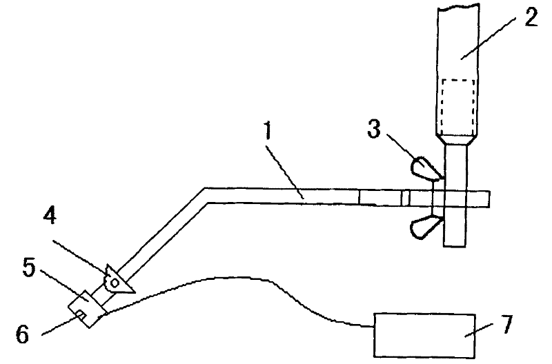
[0015] Such as figure 1 As shown, the present invention comprises a detection frame main body 1, one end of the detection frame main body 1 is connected with an insulating operating rod 2, the other end of the detection frame main body 1 is connected with a universal joint 4, and the front end of the universal joint 4 is fixed with a CCD coupling cavity mirror 5 and An intracavity cold light illumination system 6, wherein the intracavity cold light illumination system 6 is located in the CCD coupling cavity mirror 5; the above-mentioned CCD coupling cavity mirror 5 is connected to the smart terminal 7.

[0016] It should be noted that the above-mentioned detection frame main body 1 and the insulating operating rod 2 are connected through an adjusting nut 3 , so that the positional relationship between the detecting frame main body 1 and the insulating operating rod 2 can be adjusted. The above-mentioned detection frame main body 1 is a support rod with an angle of 135° in the ...

Embodiment 2

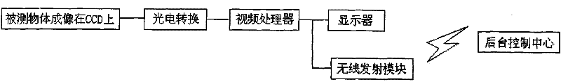
[0022] The difference between this embodiment and Embodiment 1 is that in this embodiment, the smart terminal 7 further includes a wireless transmitting module, and the wireless transmitting module is connected to the background control center. Correspondingly, the background control center should have a wireless receiving module to receive the picture information sent by the smart terminal 7. The above wireless module can use the 3G network, or a KYL-320M wireless communication module.

[0023] When the intelligent terminal is connected to the background control center by wireless means, it can also facilitate other monitoring personnel to see information in time. In this way, the monitoring personnel in the background can help the actual operating staff to perform detection, so as to prevent the actual operating staff from missing detection.

[0024] Other technical characteristics are identical with embodiment 1.


PUM


Abstract

The invention discloses an endoscope technology-based discharge-trace inspection system which comprises an inspection frame main body, one end of the inspection frame body is connected with an insulating operation rod, and the other end of the inspection frame body is connected with a universal joint, a CCD (charge coupled device) coupling endoscope and an intra-cavity luminescence lighting system are fixed at the front end of the universal joint, and the intra-cavity luminescence lighting system is arranged in the CCD coupling endoscope; and the CCD coupling endoscope is connected with an intelligent terminal. According to the invention adopting the technical scheme above, through using the operating principle of an endoscope, ground potential workers can clearly observe discharging traces from a further distance only by observing the intelligent terminal in hands without raising heads all the while, thereby greatly facilitating the practical operation of the workers. When the intelligent terminal is connected with a background control center in a wireless mode, the system also can be convenient to other monitoring workers for timely seeing the information, and help practical workers to carry out detection.

Description

technical field [0001] The invention relates to line fault inspection equipment, in particular to a discharge trace inspection equipment. Background technique [0002] When the power transmission and transformation lines encounter lightning strikes, short-circuits or flashovers of foreign objects, discharge traces will be left on the short-circuit or ground discharge points. When looking for points, there are many blind spots, which cause omissions in the inspection work. In many cases, because the discharge point cannot be found, the power must be cut off for maintenance, which wastes a lot of time. [0003] The application number is 200910251260.5, and the invention title is "a discharge trace inspection equipment". Although a discharge trace inspection technology is also disclosed, this technology must require the staff to look up at the magnifying glass, and the distance from the human eye to the magnifying glass is also Very far away, it is very difficult for staff wi...

Claims


Application Information

Patent Timeline
IPC IPC(8): G01R31/08H04N7/18
Inventor 张歆艳张占营王鑫张才俊
Owner STATE GRID HENAN ELECTRIC POWER COMPANY ANYANG POWER SUPPLY
Why Eureka
Try Eureka