Time parameter measurement system

A technology for measuring system and time parameters, applied in digital circuit testing, electronic circuit testing, etc., can solve problems such as difficulty in resolution, difficulty in implementation, jitter, etc., and achieve the effect of high measurement resolution

Inactive Publication Date: 2012-02-08
UNIV OF ELECTRONIC SCI & TECH OF CHINA
View PDF8 Cites 27 Cited by
  • Summary
  • Abstract
  • Description
  • Claims
  • Application Information

AI Technical Summary

Problems solved by technology

The higher the resolution requirement, the higher the counting pulse frequency of the counter is required. If the resolution is increased to 125ps, the CLK frequency is required to be 8GHz, which is very difficult to implement in the existing technology
Obviously, it is difficult to improve the resolution only by increasing the pulse frequency of the counter.
[0011] At the same t

Method used


Image

  • Time parameter measurement system
  • Time parameter measurement system
  • Time parameter measurement system

Examples


Embodiment

[0041] 1. Channel circuit unit

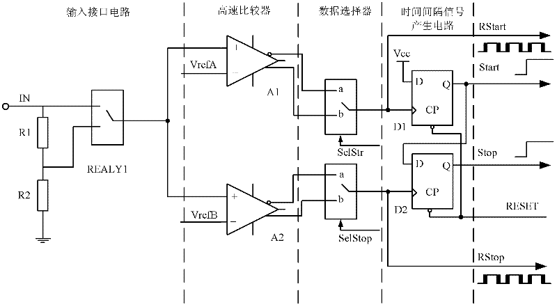
[0042] image 3 It is a principle diagram of a specific embodiment of the channel circuit unit in the present invention.

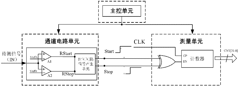
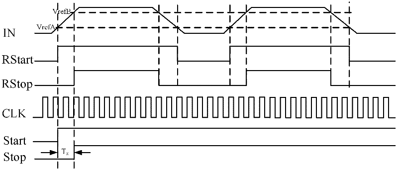
[0043] The channel circuit unit is the front end of the time parameter measurement system. In this embodiment, the channel circuit unit includes: an input interface circuit, a high-speed comparator, a data selector and a time interval generating circuit. Its function is to correctly and effectively introduce the signal to be measured into the time parameter measurement system, and convert the signal to be measured into pulse signals RStart, RStop, and time interval start signals Start and stop signals that can be recognized by the time rough measurement unit and the time fine measurement unit Stop.

[0044] Such as image 3 As shown, in this implementation, the signal IN to be tested is connected to the input interface circuit. In the input interface circuit, the resistors R1 and R2 connected in series to the ground divi...


PUM


Abstract

The invention discloses a time parameter measurement system for digital integrated circuits. The system is implemented by converting a to-be-measured signal IN into a time interval start signal Start and a stop signal Stop as well as pulse signals RStart and RStop by a channel circuit unit; then, the four signals are respectively provided for an accurate time measurement unit and a coarse time measurement unit to carry out measurement, wherein the accurate time measurement unit is composed of a multi-stage delay line and a calibration unit, and used for carrying out measurement under the condition that the rising edge of the to-be-measured signal is steep; and the coarse time measurement unit is composed of a jittering shielding circuit, a counter 1 and a counter 2 (the operating frequencies of the counter 1 and the counter 2 are complementary), and used for carrying out measurement under the condition that the rising edge of the to-be-measured signal is slow. By using the system disclosed by the invention, the difficulty of improving the resolution ratio of a time parameter measurement system for high-precision digital integrated circuits in the prior art is overcome, and the technical difficulty that the measurement bandwidth of a time parameter measurement system is limited caused by the jitter of output signals of a comparator for channel circuits.

Description

technical field [0001] The invention belongs to the technical field of electronic measurement, and more specifically relates to a digital integrated circuit time parameter measurement system. Background technique [0002] As the foundation and core of the information industry, the integrated circuit is a strategic industry for national economic and social development. It plays an important role in promoting economic development, social progress, improving people's living standards and ensuring national security. It has become the focus of current international competition. Focus and an important indicator to measure the degree of modernization and comprehensive national strength of a country or region. [0003] High-precision time parameter measurement systems play a pivotal role in the design, verification and packaging of integrated circuits. It is a powerful means of testing and verifying the qualification of integrated circuits and time-related parameters. [0004] fi...

Claims


Application Information

Patent Timeline
IPC IPC(8): G01R31/317
Inventor 詹惠琴刘凤伟古军古天祥温晓佩王敏刘田踪
Owner UNIV OF ELECTRONIC SCI & TECH OF CHINA
Why Eureka
Try Eureka