Device for distinguishing and indicating fault of thermomagnetic tripping device

A thermal-magnetic release and fault identification technology, applied in the direction of the protection switch distinguishing mark, protection switch operation/release mechanism, etc., can solve the problems of inaccurate fault indication, unreliable positioning, unreliability, etc. Assembly, the effect of a small number of parts

Active Publication Date: 2012-02-08
SHANGHAI LIANGXIN ELECTRICAL
View PDF5 Cites 16 Cited by
  • Summary
  • Abstract
  • Description
  • Claims
  • Application Information

AI Technical Summary

Problems solved by technology

This structure can also play a role in distinguishing fault types, but its disadvantages are: the fault indication surface is directly set on the first jumper and the second jumper, an

Method used


Image

  • Device for distinguishing and indicating fault of thermomagnetic tripping device
  • Device for distinguishing and indicating fault of thermomagnetic tripping device
  • Device for distinguishing and indicating fault of thermomagnetic tripping device

Examples


Example Embodiment

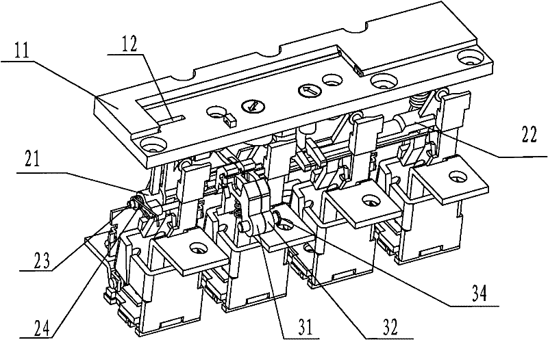
[0018] Such as figure 1 As shown, a fault identification and indication device for a thermomagnetic trip unit of the present invention includes a top cover 11, and an observation window 12 is provided on the top cover 11. Under the top cover 11, there is an instantaneous traction rod 21 and a delay traction rod 22. The instantaneous traction rod 21 and the delay traction rod 22 are rotatably mounted on the same traction rod shaft 23. The two ends of the traction rod shaft 23 are respectively A return spring 24 for resetting the instantaneous traction rod 21 and the delay traction rod 22 is provided. The instantaneous trip buckle 31 cooperates with the instantaneous traction rod 21, the delay trip buckle 32 cooperates with the delay traction rod 22, and the instantaneous trip buckle 31 and the delay trip buckle 32 are rotatably mounted on the same tripping shaft 34.

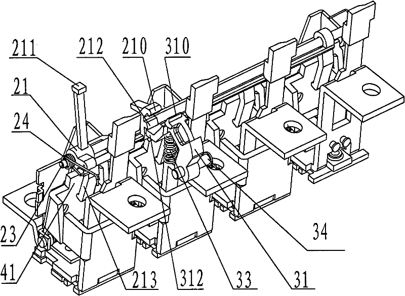
[0019] Such as figure 2 As shown, this is a schematic diagram of the present invention in a short-circuit trip st...


PUM


Abstract

The invention discloses a device for distinguishing and indicating a fault of a thermomagnetic tripping device, which comprises an observation window, a short circuit indicating face, an overload indicating face, an instant draw bar, an instant tripper, a time delay draw bar and a time delay tripper, wherein the instant draw bar is provided with an instant draw hook; the instant tripper is provided with an instant tripper hook; the instant draw hook and the instant tripper hook are buckled with each other; the time delay draw bar is provided with a time delay draw hook; the time delay tripper is provided with a time delay tripper hook; the time delay draw hook and the time delay tripper hook are buckled with each other; when the instant draw hook and the instant tripper hook are separated, the extension arm of the instant draw bar is abutted with the extension arm of the instant tripper; and when the time delay draw hook is separated from the time delay tripper hook, the extension arm of the time delay draw bar is abutted with the extension arm of the time delay tripper. The device for distinguishing and indicating the fault of the thermomagnetic tripping device is capable of clearly distinguishing the tripping reasons, has small amount of parts, a simple structure, is easy to assemble and is capable of enabling the fault indication to be more stably and reliably.

Description

technical field [0001] The invention relates to the field of low-voltage electrical appliances, in particular to a fault discrimination and indication device for a thermal-magnetic release. Background technique [0002] The thermal magnetic release is an important part of the molded case circuit breaker. It plays the role of overload protection and short circuit protection in the entire circuit breaker. Because of its stable and reliable performance, it is widely used. In the release of the existing circuit breaker, when there is an overload current in the circuit, the bimetal sheet of the thermal protection element is heated and deformed, pushing the drawbar, and then the operating mechanism is activated to disconnect the circuit; when there is a short-circuit current in the circuit, the electromagnetic The system generates electromagnetic force, and the armature moves to move the drawbar, which in turn causes the operating mechanism to act and disconnect the circuit. Howe...

Claims


Application Information

Patent Timeline
IPC IPC(8): H01H71/06H01H71/40
Inventor 刘正刚张江晏国云
Owner SHANGHAI LIANGXIN ELECTRICAL
Why Eureka
Try Eureka